Rendered from docs/PRINT_PLAN.md in the repository at build time.
Estimates are labelled as such in the source; nothing on this page is a measured result unless it says so.
BlindBot / ValiTilt print plan (design team, 2026-10-17)#
Status of this plan (2026-10-18). It was written against the round-4 export (22 STLs, 2026-10-17 evening) and is kept as written for its orientation, support, slicer and post-print-check notes. Round 5 (cost-down) has since changed several parts: the housing base slit and thin corners are fixed, the cup rim is a bullnose, the pane pack prints back down, the offset-gear cover is split into
cover_base+cover_lid, the bracket ear pitch is 35 mm, the controller box is now three versions (ebox_A_usb_*,ebox_B_battery_*,ebox_C_solar_*, replacingebox_base/ebox_lid) andcable_clipis new. Where this plan and ASSEMBLY.md disagree, ASSEMBLY.md (round 5) wins. Mesh numbers for the current STLs are on the site's parts pages, measured at build time. Every knob, rod and clip dimension below is estimated from photo, not caliper.
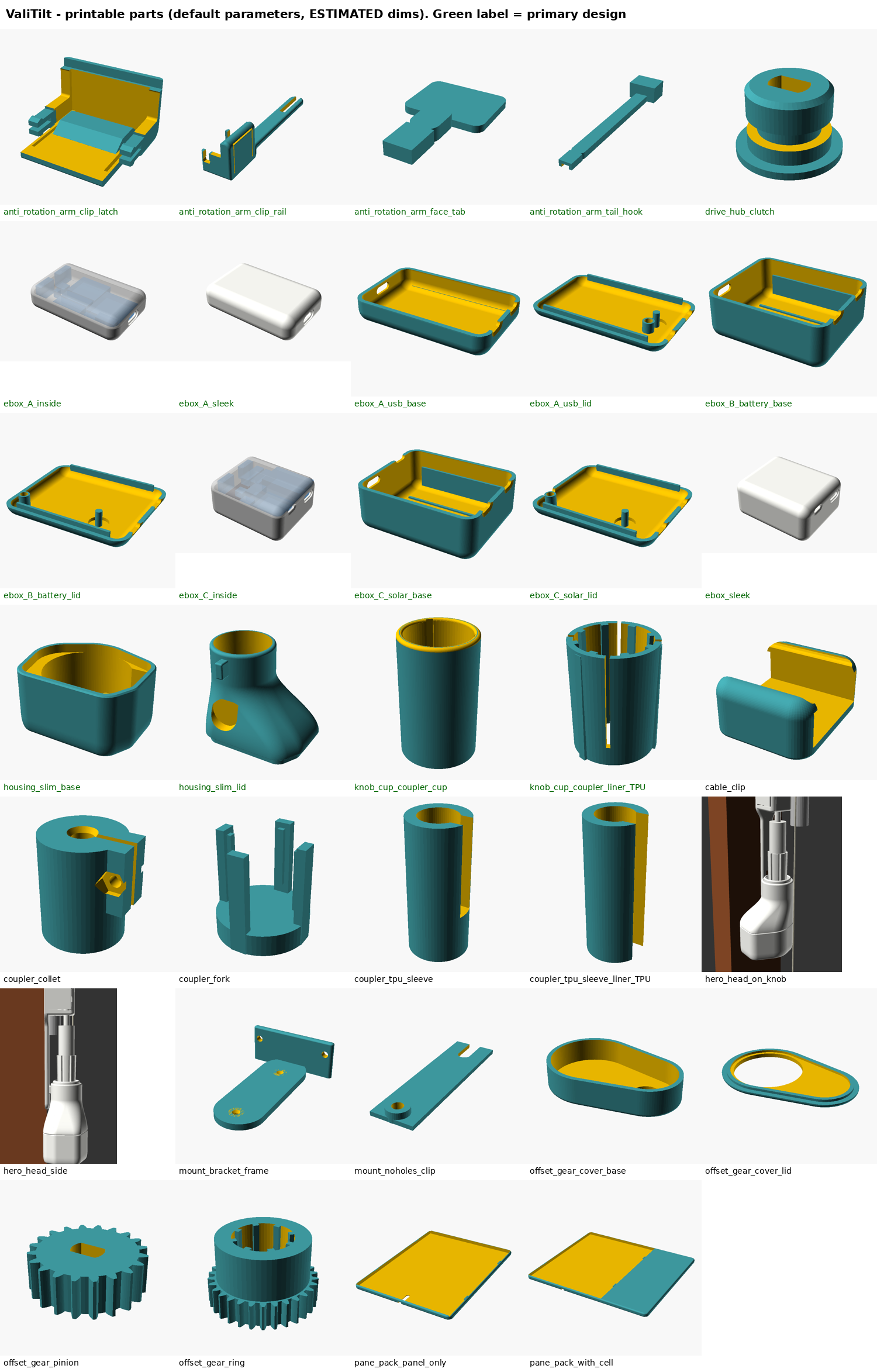
Scope. This plan covers every STL of the round-4 export in hardware/stl/: 22 files. That is the 19 from the 20:13–20:21 EEST export plus the three pane_pack_* files that appeared at 20:36 EEST while this plan was being written. I analysed a snapshot of those files. The pack is being redesigned right now, so re-check any part whose STL timestamp is newer than 20:36 EEST before you print it. Nothing in the pack was edited.
Sources. Geometry comes from the meshes (trimesh 4.x, admesh). Purposes and clearances come from cad/*.scad (cited as file:line). Field values come from the 2026-10-17 tape-in-photo readings and the M-table in DESIGN.md §12. Every knob, rod and clip dimension is a photo estimate (±1–2 mm, not caliper). Nothing here is a new measurement. Print settings are typical starting ranges, i.e. recommendations, not values verified on this design.
Method notes
- Bounding box = mesh extents in the exported orientation (X × Y × Z, Z = up on the bed).
- Solid g = mesh volume × 1.27 g/cm³ (PETG) or 1.21 g/cm³ (TPU 95A).
- g at infill is an estimate. I voxelised the mesh at 0.2 mm and eroded it by the wall thickness (perimeters × 0.42 mm) in XY and by the top/bottom layers in Z, which gives a shell. Mass = shell + infill % × core. Real slicer numbers differ by roughly ±10 %. Thin parts are effectively 100 % perimeters whatever infill you set.
- Manifold = trimesh watertight + winding-consistent + body count, plus
admesh -c(edges fixed / degenerate / backwards / facets added or removed).
0. Summary table (all 22 STLs)#
| STL | bbox mm (X×Y×Z) | vol cm³ | material | g solid | infill | g at infill (est.) | watertight / winding / bodies | faces |
|---|---|---|---|---|---|---|---|---|
anti_rotation_arm_clip_rail.stl |
17.8 x 94.4 x 21.9 | 3.87 | PETG | 4.9 | 100 % | 4.9 | yes / yes / 1 | 7004 |
anti_rotation_arm_clip_latch.stl |
24.1 x 21.9 x 14.2 | 1.55 | PETG | 2.0 | 100 % | 2.0 | yes / yes / 1 | 2568 |
knob_cup_coupler_cup.stl |
20.1 x 20.1 x 32.8 | 4.70 | PETG | 6.0 | 40 % | 5.5 | yes / yes / 1 | 3932 |
knob_cup_coupler_liner_TPU.stl |
16.8 x 16.8 x 22.0 | 1.37 | TPU | 1.6 | 100 % | 1.6 | yes / yes / 1 | 1028 |
drive_hub_clutch.stl |
13.5 x 13.5 x 9.0 | 0.62 | PETG | 0.8 | 100 % | 0.8 | yes / yes / 1 | 1684 |
housing_slim_base.stl |
38.8 x 31.9 x 21.1 | 5.21 | PETG (ASA opt.) | 6.6 | 20 % | 5.9 | yes / yes / 1 | 7296 |
housing_slim_lid.stl |
38.8 x 31.9 x 36.4 | 8.05 | PETG (ASA opt.) | 10.2 | 15 % | 7.0 | yes / yes / 1 | 11286 |
ebox_base.stl |
65.6 x 47.6 x 20.4 | 14.61 | PETG | 18.6 | 15 % | 16.3 | yes / yes / 1 | 5760 |
ebox_lid.stl |
65.6 x 47.6 x 16.2 | 10.25 | PETG | 13.0 | 15 % | 13.0 | yes / yes / 1 | 5900 |
pane_pack_panel_only.stl |
68.8 x 115.8 x 3.7 | 5.69 | PETG / ASA | 7.2 | 100 % | 7.2 | yes / yes / 1 | 5582 |
pane_pack_with_cell.stl |
115.4 x 115.8 x 4.6 | 21.83 | PETG / ASA | 27.7 | 100 % | 27.7 | yes / yes / 1 | 5330 |
pane_pack_cell_cover.stl |
46.2 x 79.2 x 0.6 | 2.19 | PETG / ASA | 2.8 | 100 % | 2.8 | yes / yes / 1 | 2716 |
anti_rotation_arm_face_tab.stl |
18.0 x 28.5 x 3.0 | 0.67 | PETG | 0.8 | 100 % | 0.8 | yes / yes / 1 | 384 |
anti_rotation_arm_tail_hook.stl |
13.4 x 74.5 x 8.0 | 1.62 | PETG | 2.1 | 100 % | 2.1 | yes / yes / 1 | 148 |
coupler_collet.stl |
18.0 x 16.0 x 20.0 | 3.81 | PETG | 4.8 | 40 % | 3.8 | yes / yes / 1 | 1698 |
coupler_fork.stl |
16.8 x 16.8 x 18.0 | 1.16 | PETG | 1.5 | 100 % | 1.5 | yes / yes / 1 | 484 |
coupler_tpu_sleeve.stl |
10.5 x 10.5 x 24.0 | 1.32 | PETG | 1.7 | 40 % | 1.6 | yes / yes / 1 | 600 |
coupler_tpu_sleeve_liner_TPU.stl |
6.2 x 6.5 x 16.0 | 0.26 | TPU | 0.3 | 100 % | 0.3 | yes / yes / 1 | 428 |
mount_bracket_frame.stl |
22.0 x 60.0 x 18.0 | 4.60 | PETG | 5.8 | 40 % | 5.1 | yes / yes / 1 | 1344 |
mount_noholes_clip.stl |
12.0 x 44.1 x 3.0 | 0.63 | PETG | 0.8 | 100 % | 0.8 | yes / yes / 1 | 436 |
offset_gear_ring.stl |
25.6 x 25.5 x 16.0 | 4.37 | PETG | 5.5 | 40 % | 4.9 | yes / yes / 1 | 3708 |
offset_gear_pinion.stl |
17.6 x 17.6 x 6.0 | 1.13 | PETG | 1.4 | 100 % | 1.4 | yes / yes / 1 | 1960 |
offset_gear_cover.stl |
46.4 x 30.4 x 10.8 | 3.73 | PETG | 4.7 | 20 % | 4.7 | yes / yes / 1 | 1040 |
Manifold result. All 22 meshes are watertight, winding-consistent and single-body. admesh reports 0 edges fixed, 0 degenerate facets, 0 backwards edges and 0 facets added, removed or reversed for every file. My numbers agree with the pack's own stl/manifold_report.txt, which covers the first 19. The mesh checks pass, but these are geometry problems found in the meshes (details in each part section):
housing_slim_base: the motor pocket breaks through the outer skin. Between z ≈ 1.6 and 3.9 mm, horizontal sections of the mesh are not a closed ring. The r=6 bottom round (round_r,housing_slim.scad:35,96) is inset by up to ~1.9 mm at the motor-pocket floor height (z 1.6), but the radial wall there is only 1.6 (body_r − pocket radius). The result is a crescent-shaped see-through slit in the bottom fillet on the motor side, plus a breach at the wire-box corner. I confirmed it in a bottom-view render of the round-4 scad, and it is also visible inrenders/visual_installed_white.pngat the lower-left corner of the head. On top of that, the wall at the two wire-box pocket corners (25.4, ±8.8) is 0.35 mm over the full height (sections at z = 8 / 12 / 17 / 20). This part should not be printed for keeps until the lead fixes it. A test print is fine for checking the motor fit. Fixes are in sleek-notes #1.knob_cup_coupler_cup: knife-edge rim. Wall at z 32.7 is 0.13 mm, and the top is 0.24 mm lower thancup_hbecause the 1.5 mm lead-in chamfer meets the r=1 outer round. See §2.housing_slim_lidSTL starts at z = 0.2, not 0. The slicer drops it to the bed, so this is harmless.pane_pack_*(pack/with_cell): the four snap hooks reach z = −0.4, below the body. In the scad's stated orientation ("front down") the body would float 0.4 mm and the panel pocket ceiling would be a 66 × 113 mm bridge. See §9.offset_gear_coveris one closed piece. Its top hole is Ø22.8 and the ring gear tip diameter is 25.6, so the gears cannot be put inside it. It is a fallback part only. See §16.mount_bracket_frame: the motor ear holes are 17.5 mm apart (x*0.5atmount_bracket_frame.scad:19), butmotor_hole_pitch = 35. Secondary part. See §14.
1. anti_rotation_arm_clip_rail.stl + anti_rotation_arm_clip_latch.stl: PRINT FIRST (the first test print)#
Update 2026-10-18 (two pieces). The one-piece part described below could not be fitted: its rail had to pass through the rod and knob when pushed on from the room side. The hood is now split around the rod (DESIGN.md §4.3):
clip_rail= rail + fork + the hood's back strips behind the rod + right side wall/tongue (prints on its back as below; outside now 17.8 × 21.9 × 24.1, top/bottom walls 2.4, a 7 × 7 rod hole instead of the slots, two 3.6 mm snap slots through the back strips), and the newclip_latch= left side wall/tongue + front of the hood + two split-arrow snap tongues.clip_latchprints on its left outside face (as exported): the side wall lies flat on the bed, the walls and the snap tongues stand upright, so the side-wall tongue and the snap prongs flex in the layer plane; no supports, no bridges. PETG, same settings as below (4 perimeters, 100 %): 1.55 cm³ ≈ 2.0 g solid (clip_railnow 3.87 cm³ ≈ 4.9 g). Check after printing: snap slit 1.0 open over 5 mm, both prongs spring back, snap slots inclip_rail3.6 wide. On the window: fitclip_railfirst (slide it in sideways along the frame face from the side away from the hinge), then pushclip_latchon from the room until both snaps click (ASSEMBLY.md §4 step 2). The tests below apply to the pair; line references (:NN) are to the pre-2026-10-18 file.
What it is (anti_rotation_arm.scad:10-20, 111-163, default part="clip_rail"). This is the reaction arm that keeps the motor head from rotating. A hood pushes onto the existing screwed white rod guide clip from the room side. Two flexible tongues in its side walls grip the clip's tab wings over an 11–14 mm range, slots in its top and bottom walls let the rod and ferrules pass, and its top wall rests on the clip top. A 10 × 3 mm rail runs 73 mm down the frame face behind the knob. A 24 mm fork at its lower end takes the 3 mm key (rail_lug) on the back of the housing collar. It carries reaction torque only. The head's weight stays on the knob.
Key dimensions (derived from the scad defaults):
| feature | value | source |
|---|---|---|
hood pocket width iw |
14.6 (= clip_w_max 14 + 2 × clip_fit 0.3) | :43,47,112 |
| free gap between the tongue bumps | 10.6 (= clip_w_min 11 − 0.4); bump height 2.0 per side | :42,116 |
pocket depth id (out from the frame face) |
20.3 (= clip_proj 20 + 0.3) | :45,112 |
pocket height ih |
19.3 (= clip_h 19 + 0.3) | :39,112 |
| hood outside | 17.8 wide × 21.9 deep × 22.5 tall, walls 1.6 | :49,113 |
| tongue | root 3 mm from the face, free end at 19.5, 16.3 long in z, 1.6 thick; slits 0.7 (long sides) and 0.8 (free end) | :117-118,143-148 |
| bump plateau | 12–17 mm out from the face | :51 |
| rod/ferrule slot | 7.0 wide, open toward the face, round end centred 16 out (reaches 19.5) | :46,48,141-142 |
| rail | 10 × 3, front edges r 1.4, back edges r 0.5 | :52-53,98,103-106 |
| fork slot | 3.6 wide (key 3.0 + 2 × 0.3), from the rail tip (0.34 above the knob-tip level) to 24 | :55-59,150 |
| hood position | clip bottom 73 / top 92 above the knob tip | :36-40 |
Orientation: as exported, frame-face (back) side on the bed#
The STL is already in this orientation (rotate([90,0,0]) at :166, "print lying on its back").
- Bed face = the rail's flat back plus the open back rim of the hood: 639 mm² of contact. Print X = across the frame face, print −Y = up the window, print Z = out from the frame face. The hood is a 21.9 mm-tall U standing on the bed, and the rail lies flat (3 mm tall).
- Why. (a) The rail's layers run along its length. The reaction load from the key bends the rail sideways in the plane of the frame face, which is in-layer bending: the strongest way to print a long, thin bar. (b) The back that bears on the frame face comes out bed-flat. (c) No supports are needed. (d) The room-facing front of the hood is the last, top surface, so it gets a clean top skin.
- The trade-off: tongue flex vs layer lines. Each tongue's length runs along print Z (root at Z = 3, free end at Z = 19.5), and it flexes in print X. Its bending stress therefore runs across the layer lines, the weakest direction. Rough estimate (beam formula ε ≈ 1.5·t·δ/L², t = 1.6, lever L ≈ 11.5 mm to mid-plateau, deflection δ = (wing − 10.6)/2):
| wing | deflection per side | strain (est.) |
|---|---|---|
| 11 mm | 0.2 mm | ≈ 0.4 % |
| 12 mm | 0.7 mm | ≈ 1.3 % |
| 13 mm | 1.2 mm | ≈ 2.2 % |
| 14 mm | 1.7 mm | ≈ 3.1 % |
These are estimates. Interlayer failure strain of PETG is lower than bulk and depends on the printer. Wings at 13–14 mm risk cracking the tongue root. Settings below mitigate this. If cracks still appear, see "what to change".
- Other orientations are worse. Hood-side-down leaves the 73 mm rail floating 3.9 mm above the bed, so the whole rail needs support. Standing up (world-z vertical) puts the rail's bending across layers and gives a 94 mm wobbly tower.
Supports and brim#
- Supports: none. Turn auto-supports OFF for this part. The only real overhang is the inside of the hood's front wall: a flat ceiling of 326 mm² at print Z 20.3 that spans the 14.6 × 19.3 mm pocket. Bridge it (bridge fan 100 %, bridge speed 20–30 mm/s, bridge flow 0.9–1.0). The slicer should pick the 14.6 mm span. Do not let supports grow inside the pocket. They fuse to the tongues and the bumps and are almost impossible to remove. If your slicer insists, paint a support blocker over the whole hood interior. The round ends of the rod slots are arches (≤ 9 mm² each) and print fine.
- Brim: not needed (639 mm² contact, PETG warps little). If your bed lets small tips lift, add 5–6 mm mouse ears at the two fork prong tips (each prong 3.2 wide) and the four hood corners.
- Elephant-foot compensation 0.10–0.15 mm. The first layer forms the mouth of the fork slot and the hood pocket. Squish there narrows exactly the fits you are testing.
Slicer settings (recommendations)#
- PETG, 0.4 nozzle, 0.16–0.20 mm layers (0.16 gives the tongue slits more layers to resolve). Line width 0.42–0.45.
- 4 perimeters. The 1.6 mm hood wall then becomes all perimeters with no infill seam in the tongues. 5 top / 5 bottom layers. Infill 100 % rectilinear or monotonic, aligned along the rail (0°/90°) if your slicer allows. 6.0 g.
- Nozzle 240–250 °C (upper end of PETG for layer bonding at the tongue roots), bed 75–85 °C, part fan 30–40 % (bridges 100 %).
- Outer walls 25–35 mm/s, first layer 15–20 mm/s.
- Z-seam: aligned and placed on the hood's lower face, the face the rail leaves from (print +Y side of the hood), which points down when installed. Keep it off the room-facing front and the side walls.
- Turn off "thin wall"/gap fill in the slits if it bridges the 0.7 mm gaps. Arachne default is usually fine.
What to measure after printing (on the bench, before the window)#
Use a caliper if you have one. Otherwise use the taper gauge from tolerance_coupons.scad (see §T).
| check | target | pass |
|---|---|---|
| pocket width at the mouth (bed side) and at the front | 14.6 | 14.4–14.8 |
| free gap between the two bumps | 10.6 | 10.4–10.9 |
| pocket height (inside top wall → inside bottom wall) | 19.3 | 19.1–19.5 |
| pocket depth | 20.3 | 20.1–20.5 |
| fork slot width over its full length, including the first layer | 3.6 | 3.45–3.75 |
| rail thickness | 3.0 | ±0.15 |
| rod slot width | 7.0 | ±0.2 |
| rail flatness: lay the back on glass | — | gap ≤ 0.3 mm over 94 mm |
Tongues free: all three slits open on both tongues. Check especially the 0.8 mm free-end slit under the front-wall bridge, print Z 19.5–20.3: if the bridge sags 0.3–0.5 mm it can fuse the tongue tip. Each tongue must move on its own when pushed with a fingernail. Clear a fused slit with a knife.
Flex test: flex each tongue outward about 1.5 mm, 10 times. Pass = no white stress marks or cracks at the root (Z ≈ 3).
Test on the window: pass/fail#
- Hood onto the clip: it slides on from the room side with thumb pressure, without twisting the rod or moving the clip. It pulls off by hand. After 10 on/off cycles: no whitening or cracks. FAIL if it won't go on, needs a tool, or cracks.
- Seat: the hood's top wall rests on the clip top, and the rail's back lies flat on the frame face (a sheet of paper should not slide under the rail just below the hood; gap ≤ 0.5 mm). FAIL if the hood front bottoms out on the tab tip first. That means the depth is too shallow.
- Rod and ferrules: they pass through the slots without rubbing, and the knob still turns by hand as easily as before.
- Reaction: push the fork end sideways with a finger. The hood must not rotate or walk off the clip. Small play (about 1 mm at the fork, estimate) is fine.
- Fork height (the geometry check): measure the rail's lower end relative to the knob tip with the knob hanging free. Design = 0 mm (rail end level with the tip). The key at 12–18 mm above the tip stays engaged if the rail end is between −6 and +12 mm (
:57-59, DESIGN.md). FAIL outside that range: change the rail length, not the fit (see below). - Cords: run the lift cords past the hood. They must not catch on its corners or slots.
What to change if it fails (parameters in anti_rotation_arm.scad; the lead folds these in, I edited nothing)#
- Hood won't go on (height): the clip is taller than 19.3 mm. Measure the clip height with gauge C, then set
clip_h(:39) to that value. Better: add a separate height fit (the pocket usesih = clip_h + clip_fitat:112; make itclip_h + clip_fit_hwithclip_fit_h0.5–1.0). Extra height play is harmless because gravity seats the top wall and the reaction torque is horizontal. As a quicker check, print the hood coupons with h_fit 0.1 / 0.3 / 0.5 (§T). - Too tight in width (hard push, tongue whitening; wings ≥ 13 mm): raise the free gap. Change
clip_w_min - 0.4at:116to (measured wing − 0.4). Or shorten the ramp by narrowingtongue_bump_plateau(:51). Do not thin the hood wall below 1.2 mm. - Too loose (falls off, hood rotates around the rod): lower the free gap to (measured wing − 0.6), or reduce
clip_fitacross the width only. - Depth: if the hood bottoms out on the tab tip, set
clip_proj(:45) to the measured value. If it rattles in and out, reduce it. - Fork misses the key: set
clip_top_above_tip(:36) to the measured clip-top height above the knob tip. See the measurement mismatch below: this one is likely. - Key binds in the fork (usually first-layer squish): elephant-foot compensation 0.15, or
key_play(:56) 0.3 → 0.35. Head rattles:key_play0.2. Check with the fork/key coupon first. - Tongue cracks at the root: print at 245–250 °C with fan ≤ 30 % and 0.16 mm layers. If it still cracks, redesign the tongue (design suggestion for the lead): run the tongue along world z, rooted at the hood's top wall and free toward the bottom wall. In this same print orientation its length then lies in the layer plane, so it flexes along the layers. Also round the slit ends (r 0.3–0.4 hull of cylinders instead of the
cubecuts at:145-147) to remove the stress raisers at the root.
Key tolerance to check first. It is not a tolerance at all: it is clip height versus the 19.3 mm pocket (0.3 mm total clearance on a ±2 mm photo estimate), then the wing width versus the 10.6 / 14.6 grip window. Both are photo values. Measurement mismatch: the tape photo readings (2026-10-17) gives the rod guide clip at about 44–47 cm on the tape and the knob tip at 56.5 cm. That puts the clip bottom about 95 mm above the tip (and its top about 125 mm if 44–47 is its extent). The scad uses 73 / 92 mm from later ruler photos (DESIGN M26). 95 − 73 = +22 mm, outside the fork's +12 mm range, so if the tape reading is right, the printed rail is about 10 mm too short and the fork misses the key. The hood fit test does not depend on this: you can test the hood on the clip without the head. Measure clip-bottom → knob-tip with a ruler on the window before relying on the rail length. The tape reading also puts the clip above the hinge barrel (top 48.4 cm = 81 mm above the tip), whereas the scad's clip (73–92) overlaps the barrel's height band (56–81). Laterally they are still ≥ 12 mm apart: barrel inner edge 21 mm from the rod axis (photo readings) vs hood half-width 8.9.
2. knob_cup_coupler_cup.stl (PRIMARY coupler)#
- Purpose (
knob_cup_coupler.scad:1-8): a closed cup that pushes up over the fluted knob from below. The TPU liner carries the splines. Its bottom skirt is the female half of the O-ring slip clutch. - Orientation: as exported, clutch-bore end down, mouth up. The tapered knob bore and its lead-in are then open-topped. The floor (z 9–11) bridges the Ø11.4 clutch bore with a 2.5 mm vent hole in it: a 97 mm² ring-shaped ceiling. Supports: none (any support inside an 11.4 mm bore would be hard to remove). Sag of 0.2–0.3 mm is harmless because the hub is 8 mm tall in a 9 mm bore. No brim needed (196 mm² contact). The outside is a single cylinder at $fn 144. Its layer lines run around the part, which is the right way for the visible surface. Put the Z-seam on the frame side (it rotates, so seam position matters only for looks).
- Settings: PETG, 0.12–0.16 mm, 4 perimeters (the wall is 1.6–2.0, so all perimeters), 6 top/bottom, 40 % gyroid (practically everything is perimeters). 245 °C / 80 °C. 6.0 g solid, ≈ 5.5 g.
- Issue: the rim is a knife edge. Wall at z 32.7 is 0.13 mm.
lead_in = 1.5(:27, used at:72) runs into the r=1 top round (:59-60), and the rim is the most visible edge of the moving part. In slicing it becomes one wobbly line or vanishes. See sleek-notes (top-5 #3). Until it is fixed, expect a slightly ragged rim, or sand it.
3. knob_cup_coupler_liner_TPU.stl (PRIMARY, TPU: the liner)#
- Purpose (
:78-96): a TPU 95A split-finger liner with 8 internal splines (1.4 × 0.8) that drop into the knob's 8 flutes. It takes up the knob taper and the tolerances. Three outside keys stop it turning in the cup. - Orientation: as exported, solid 4 mm ring end down (the fingers are free toward the top). Contact is 64.5 mm² on a 22 mm-tall thin part, so use a 3 mm brim. TPU sticks hard to smooth PEI, so use glue stick as a release or a textured sheet. No overhangs (the splines are tapered hulls, < 45°). Supports: none.
- Settings: TPU 95A, 0.4 nozzle, 0.16–0.20 mm, 3 perimeters (the 1.2 wall becomes solid), 100 %. Nozzle 215–235 °C, bed 40–60 °C, fan 50–100 %. Speed 15–30 mm/s on direct drive (outer walls ~15–20); on Bowden ≤ 15 mm/s. Retraction short (0.5–1.5 mm direct, slow 20–30 mm/s) or off. Keep the volumetric flow at about 2–3 mm³/s or less. Dry the filament first (about 50–55 °C for a few hours; typical, check your spool). 1.6 g.
4. housing_slim_base.stl (PRIMARY housing, motor half)#
- Purpose (
housing_slim.scad:1-11, 96-106): a rounded pebble holding the 28BYJ-48 with its ears snipped off. It also has a cable exit, a socket for the optional face tab, and a spigot recess for the lid. - Orientation: as exported, flat bottom on the bed, open rim up (431 mm² contact). This matches ASSEMBLY.md. Note: the scad header says "Print the base rim-down" (
:11), but the export and ASSEMBLY.md are bottom-down, so the header is the inconsistent one. Why bottom-down: rim-down would turn the 1.6 mm floor into a ~29 mm bridge over the motor pocket. Its sag would land directly on the motor's z stack (hub_gapis only 0.3). - Overhangs: the bed-side r=6 bottom round (
round_r,:35, 96). The first ~1.7 mm of the fillet overhangs 47–78° from vertical (283 mm²). It prints without support, with a slightly rough lowest ring. Use elephant-foot compensation 0.15 and, if available, variable layer height 0.08–0.12 over the first 2 mm. The design fix is a 45° bed chamfer (sleek-notes). The tail socket ceiling (6.4 mm bridge, z 7) and the cable hole print fine. Supports: none. Brim: no. - Settings: PETG (or ASA for heat and UV next to the glass, as the pack suggests), 0.16 mm, 3 perimeters, 5 top/bottom, 20 % gyroid. 240 °C / 80 °C. Z-seam on the back (frame side, −Y). 6.6 g solid, ≈ 5.9 g.
- Issues (fix before the final print): (1) Through-slit in the bottom round between z 1.6 and 3.9: the motor pocket (Ø28.7, from z 1.6) cuts through the r=6 fillet on the motor side and at the wire-box corner. The slicer will show open gaps in those layers. (2) 0.35 mm wall at the wire-box pocket corners (x 25.4, y ±8.8;
CIRCcorner circles r=4 at:82-84vspocket2dat:92-95), so expect a hole or a single line there. Both are design fixes (sleek-notes #1): a squashed bottom round (horizontal 1.2 × vertical 5) or round_r ≤ 3, and corner circles re-centred so the wall stays ≥ 1.6. Printing it now is fine as a motor-fit test only.
5. housing_slim_lid.stl (PRIMARY housing, collar half)#
- Purpose (
:107-163): an S-blended collar that hugs the rotating cup (0.4 mm gap). It has a hidden spigot into the base, therail_lugkey (12–18 mm above the knob tip) and the rail clearance groove. - Orientation: as exported, spigot down, collar up (the STL starts at z 0.2; the slicer drops it). Collar-down would hang the whole S-blend over air.
- Supports: yes, on the build plate only. (a) The 1.75 mm ledge all round the spigot at z 3.0 (178 mm²). This is the face that sits on the base rim, so its flatness is the visible seam: support it with normal or snug supports, top Z distance 0.2 mm, 2 interface layers. (b) The flat ceiling inside the spigot over the motor and wire-box clearance at z 3.2 (356 mm²). It is hidden, so tree or normal support is fine, or you can let it bridge since it does not touch the motor. Paint blockers on the outer S-surface and the collar so nothing touches the visible skin. The key's underside (≈ 10 mm², rounded) needs no support. No brim (117 mm² on the spigot ring plus supports). If it rocks, add a 3 mm brim.
- Settings: PETG/ASA, 0.12–0.16 mm (the S-blend shows terracing at 0.2), 3 perimeters, 5 top/bottom, 15 % gyroid. 240 °C / 80 °C. Z-seam on the back (frame side, inside the rail groove if possible). 10.2 g solid, ≈ 7.0 g.
6. drive_hub_clutch.stl (PRIMARY, male half of the clutch)#
- Purpose (
drive_hub_clutch.scad:1-7): a hub that press-fits on the 28BYJ-48 D-shaft. It carries one 8×2 NBR O-ring in a groove, and the O-ring squeezes in the cup's clutch bore to make a friction slip clutch. - Orientation: as exported, flange down. The D-bore is vertical, so the flats are accurate and round. The O-ring groove's top (z 5.15) is a 1.3 mm-deep ring-shaped overhang and the D-bore entry cone is small. Both print unsupported. Supports: none. No brim needed (117 mm²), but a 2 mm brim helps a 13.5 mm part stay put.
- Settings: PETG, 0.12 mm, 4 perimeters, 100 %, 240 °C / 80 °C. Print 2–3 at once (spares, and a slower layer time for small parts). Minimum layer time ≥ 8 s, or print alongside other parts. 0.8 g.
7. ebox_base.stl (controller box, base)#
- Purpose (
ebox.scad:1-13, 44-60): the base of the room-side controller box (XIAO ESP32C6 + drivers, optional LiPo bay, USB-C, cable exits, perfboard ledges). Exported variant:liion_solar(:15). - Orientation: as exported, bottom down. The R=6 sphere-rounded bottom edges near the bed overhang strongly in the lowest 1.5 mm (583 mm² at 0–39° from flat). They print with a rough first ring, so use elephant-foot compensation 0.15. All openings are horizontal holes in the end walls: the USB-C stadium has a 6 mm flat top bridge, the cable holes are Ø3.4 and Ø2.6. Supports: none. No brim.
- Settings: PETG, 0.2 mm, 3 perimeters, 5 top/bottom, 15 % gyroid, 240 °C / 80 °C. Z-seam at a rear corner. 18.6 g solid, ≈ 16.3 g. Note:
ebox.scadchanged at 20:34 (newliion_packvariant), but the STL is still the 20:21liion_solarexport.
8. ebox_lid.stl (controller box, lid)#
- Purpose (
ebox.scad:61-80): the lid, with the locating lip, pinhole LED, and C-slot flexure button. - Orientation: as exported, top face on the bed (smooth visible top, button and LED crisp). The R=6 bed-side edges have the same rough first ring as the base (elephant-foot compensation 0.15). The lip's joining ring is an internal 1.35 mm ledge at z 12.7 (270 mm²) and prints unsupported. Supports: none. No brim.
- Settings: as the base. A textured or smooth PEI gives the top finish you want. 13.0 g.
9. pane_pack_panel_only.stl / pane_pack_with_cell.stl / pane_pack_cell_cover.stl (new at 20:36)#
- Purpose (
pane_pack.scad:1-12): a flat inter-pane solar pack holding a 66 × 113 × 2.6 mm panel (and, inwith_cell, a 2.9 × 45 × 75 mm LiPo beside it), with four 0.4 mm snap hooks. Mounting is not designed yet. - Orientation problem: the scad says "Print front (glass side) down" (
:12). In that orientation (a) the snap hooks hang 0.4 mm below the body (STL z −0.4), so the body floats, and (b) the panel pocket opens toward the glass, so its 0.6 mm back wall becomes a 66 × 113 mm flat bridge at z 2.7 (7530 mm² of ceiling). That is not printable. - Recommendation: flip it, back face (z = T) on the bed.
panel_only: the 0.6 mm back is 3 layers on the bed, the panel pocket opens upward, and the hooks become tiny features on top. Supports: none.with_cell: the cell pocket then opens toward the bed, so its 0.4 mm glass-side skin is a 45 × 78 mm ceiling. Supports from the build plate inside the cell pocket (normal, 0.2 mm top gap). They remove through the open back.cell_cover: flat, as exported, no supports.
- Settings: PETG or better ASA (between the panes in sun it can get hot; PETG softens around its Tg ≈ 80 °C, a typical value). 0.2 mm layers (
back_t0.6 = 3 layers,skin_t0.4 = 2 layers,pane_pack.scad:21-22), 3 perimeters, 100 % (thin). 240 °C / 80 °C for PETG. Use a 5 mm brim on the 115 mm-widewith_cellpart against corner lift. Mass 7.2 / 27.7 / 2.8 g.
10. anti_rotation_arm_face_tab.stl (last resort, adhesive)#
- Purpose (
anti_rotation_arm.scad:8-9, 81-90): a short tenon into the housing socket plus an 18 × 14 pad for a 3M VHB square. It conflicts with the no-glue rule, so print it only if the clip rail fails. - Orientation: flat as exported (334 mm² on the bed). The pad is bed-flat for the VHB. No supports, no brim. PETG, 0.2, 3 perimeters, 100 %, 0.8 g.
11. anti_rotation_arm_tail_hook.stl (obsolete reference)#
- Purpose (
:4-7, 66-80): a tail with a saddle that docked on a white hook below the knob. No hook exists (photo readings: "nothing below the knob"). Don't print it unless the window changes. - If printed: flat as exported. The cable groove (3.4 mm) and the saddle tunnel (9.6 mm, z 6.5) are bridges with no supports. PETG 0.2, 100 %, 2.1 g.
12. coupler_collet.stl (secondary concept)#
- Purpose (
coupler_collet.scad:1-5): a split clamp collet on the thin grey rod below the L-bracket, with an M2 screw and nut trap and a D-bore for the motor shaft. It needs a separately mounted motor. - Orientation: as exported, D-bore end down. The D-bore ceiling is a 5 mm bridge. The horizontal M2 hole and the hex nut trap have small overhangs (≤ 8 mm²). No supports. PETG 0.16, 4 perimeters, 40 %, 4.8 g solid / ≈ 3.8 g. The slot faces become vertical walls, so the clamp flexes across layers. Keep the screw torque gentle.
13. coupler_tpu_sleeve.stl + coupler_tpu_sleeve_liner_TPU.stl (secondary concept; the second TPU liner)#
- Purpose (
coupler_tpu_sleeve.scad:1-4): a slide-on slotted PETG sleeve on the grey rod with a TPU friction liner, plus the motor D-bore. - Sleeve: upright as exported (72 mm² contact; 3 mm brim recommended for a 24 mm-tall Ø10.5 part). The D-bore ceiling is a 5 mm bridge. No supports. PETG 0.16, 4 perimeters, 1.7 g.
- Liner (TPU): upright as exported. Only 16 mm² of contact on a 16 mm-tall C-section, so 5 mm brim, or print it beside the sleeve to share cooling time. TPU 95A, 0.16, 3 perimeters, 100 %, same TPU temperatures and speeds as §3. 0.3 g.
14. mount_bracket_frame.stl (secondary concept)#
- Purpose (
mount_bracket_frame.scad:1-4): a screwed plate (2 × 3.0 mm countersunk wood screws) with an upright flange for a 28BYJ-48 with its ears kept. - Orientation: plate down as exported (1232 mm²). The countersinks open upward, so they need no support. The motor holes are horizontal Ø3.2. No supports. PETG 0.2, 4 perimeters, 40 %, 5.8 g / ≈ 5.1 g.
- Bug: the motor holes are at x = ±8.75 (
x*0.5,:19), 17.5 mm apart, butmotor_hole_pitch = 35(:7). Fix it before printing.
15. mount_noholes_clip.stl (secondary concept)#
- Purpose (
mount_noholes_clip.scad:1-6): a 1.2 mm plate clamped under the existing L-bracket screw, with an anchor eye. M16 is not measured. - Flat as exported, no supports, PETG 0.2, 3 perimeters, 100 %, 0.8 g.
16. offset_gear_ring.stl / offset_gear_pinion.stl / offset_gear_cover.stl (fallback)#
- Purpose (
offset_gear_drive.scad:1-6): a side-mounted motor driving the knob through a 20/30 spur pair (m 0.8). The ring gear is also a spline cup on the knob, and the cover must enclose the gears because of the lift cords. - Ring: gear face down as exported, no supports, PETG 0.12 mm (m 0.8 teeth), 4 perimeters, 40 %, 5.5 g / ≈ 4.9 g.
- Pinion: flat, 0.12 mm, 100 %, 1.4 g.
- Cover: a closed box with a 27.6 mm-wide internal ceiling at z 9.4 (523 mm²) to bridge or support. Not assemblable as one piece: the top hole is Ø22.8 and the ring tip diameter is 25.6, and the motor-boss hole Ø10 is smaller than the pinion (17.6). It needs to be split into two halves before it is worth printing.
T. Fit tolerances to test first#
All interfaces, with nominal clearance from the scad versus what the measurements say. "Photo" means a tape or ruler photo reading (±1–2 mm). Radial and per-side values are labelled.
| # | interface | scad nominal (file:line) | clearance | vs measurements | risk |
|---|---|---|---|---|---|
| 1 | hood pocket height ↔ rod guide clip | ih 19.3 = clip_h 19 + 0.3 (anti_rotation_arm:39,47,112) | 0.3 total | DESIGN M26 ruler photo 19 ±2; tape (photo readings) ambiguous | HIGH: a clip > 19.3 blocks the hood |
| 2 | hood tongues ↔ tab wings | pocket 14.6, bump gap 10.6 (:41-43,116) | grips 11–14; preload 0.2/side at 11, 1.7/side at 14 | DESIGN M26 photo 11–14 | MED–HIGH (tongue strain at 13–14) |
| 3 | hood depth ↔ tab projection | id 20.3 vs clip_proj 20 (:45,112) | 0.3 | photo 19–20 | MED |
| 4 | rod/ferrule slots | 7.0 wide, round end at 16 (:46,48,141) | rod Ø4.5 → about 1.25/side | rod 4–5 (photo readings, "needs a caliper"); ferrule Ø not measured; rod axis 16 (DESIGN M12, not in the meas. file) | MED |
| 5 | fork slot ↔ housing key (vertical) | key 12–18 above the tip; slot 0.34–24 (:57-59,150; housing_slim:111) | covers the rail end at −6 … +12 | tape: clip bottom ≈ 95 above the tip vs scad 73 → +22, outside the range | HIGH (rail length) |
| 6 | fork slot ↔ key (width) | 3.6 vs lug_w 3.0 (:55-56; housing_slim:50) | 0.3/side | — | MED (first-layer squish) |
| 7 | rail ↔ lid rail groove | groove 11 × 3.5 vs rail 10 × 3 (housing_slim:54-55) | 0.5/side, 0.5 deep | — | LOW |
| 8 | rail behind the knob | rail_t 3 at the face; knob back 8–10 from the face | 5–7 | DESIGN M12 photo | LOW |
| 9 | knob flutes ↔ TPU liner splines | liner ID tip 13.6 = 13 + 2 × 0.3; at 22 mm engagement 14.46; splines 1.4 × 0.8, 8 off (knob_cup_coupler:13,20,25-26,79-80) | 0.3 radial | tip ≈ 13 ±1 (photo readings); 8 grooves ✓; fluted 41 ✓; collar→tip 42 ✓; M3 (top Ø) and M7 (flute width/depth) not measured | HIGH: ±0.5 radial uncertainty > 0.3 clearance |
| 10 | liner ↔ cup bore | cup bore tip 16.0 vs liner OD 15.9 (:42,83); keys 1.5 in 1.8 slots, 0.2 radial (:75,85) | 0.05 radial; keys 0.15/side | — | LOW–MED (TPU) |
| 11 | cup ↔ collar | cup OD 20.06 in Ø20.86 (housing_slim:27,31,137) | 0.4 radial | — | LOW (cords: keep < cord Ø/2) |
| 12 | clutch: O-ring ↔ cup bore | groove root 8.0 + 2 × 2.0 = 12.0 vs bore 11.4 (drive_hub_clutch:25-26; knob_cup_coupler:45) | 0.3 radial squeeze; hub body 10.6 → 0.4/side | O-ring 8×2 assumed | MED (slip torque) |
| 13 | D-shaft ↔ hub bore | 5.1 / 3.1 flats vs 5.0 / 3.0 (drive_hub_clutch:9-11) | 0.05/side | 28BYJ-48 typical, not measured | MED: printed holes run 0.1–0.2 small |
| 14 | motor ↔ base pocket | Ø28.7 (gap 0.35), wire box 17.7 wide (housing_slim:18-25,92-95) | 0.35/side | motor typical, not measured | MED, plus the pocket breaks through the bottom fillet (z 1.6–3.9) and leaves a 0.35 mm corner wall |
| 15 | lid spigot ↔ base recess | 0.15/side (housing_slim:41,101,132) | 0.15 | — | MED (push fit, no screws) |
| 16 | motor boss ↔ lid | Ø10 for a Ø9 boss (:139) | 0.5/side | typical | LOW |
| 17 | tail socket ↔ tenon (face tab) | 6.4 × 3.4 vs 6.0 × 3.0 (housing_slim:43; anti_rotation_arm:27-28) | 0.2/side | — | LOW (last resort) |
| 18 | cable exits | housing Ø3.2 (:44); ebox Ø3.4 / panel Ø2.6 (ebox:24) | — | cable Ø not measured | LOW |
| 19 | USB-C opening | stadium 9.6 × 3.6 (ebox:21) vs plug overmould "~8.3 × 2.5" (comment, estimate) | ≈ 0.65 / 0.55 per side | — | LOW (align with the board) |
| 20 | ebox lid lip ↔ base | fit 0.15/side, lip 2 (ebox:25,72-79) | 0.15 | — | LOW |
| 21 | collet ↔ rod; M2 screw/nut | bore 4.3 (4.5 − 0.2) (coupler_collet:6,12); screw 2.2; nut AF 4.2 | −0.1 radial (clamp) | rod 4–5, unverified | MED (secondary) |
| 22 | TPU sleeve stack | liner ID 4.2 vs rod 4.5; sleeve bore 6.7 vs liner OD 6.5; slots 3.3 / 2.7 (coupler_tpu_sleeve:6-10,16,21-23) | −0.15 press; 0.1 radial | rod unverified | MED (secondary) |
| 23 | fork claw ↔ knob | bore 13.6 (13 + 2 × 0.3), teeth 1.0 (coupler_fork:5-8) | 0.3 | tip ±1 | MED (secondary) |
| 24 | gears | m 0.8, backlash 0.1, centre distance 20; ring hub exit +0.6/side; cover gap 1.0 (offset_gear_drive:8,12) | — | — | fallback only |
| 25 | wood screws / motor ears (bracket) | Ø3.4 for 3.0 screws, countersink 6.5; ears Ø3.2 at 17.5 pitch (bug) (mount_bracket_frame:6-7,19) | 0.2/side | — | secondary |
| 26 | L-bracket screw slot | 3.6 (mount_noholes_clip:9) | — | M16 not measured | secondary |
| 27 | pane pack panel / cell / cover | panel pocket +0.2/side, +0.1 deep; cell +0.2/side, +0.3 swell; cover 0.2/side; hooks 0.4 (pane_pack:16-25) | — | panel = Voltaic data; cell = listing | MED (measure the real parts) |
Quick tolerance test plan (SUGGESTION; nothing in the pack edited)#
The design team wrote tolerance_coupons.scad (not in this repository yet). It is self-contained: the values are copied from the pack with file:line comments, and the helpers are copied from sleek.scad, so it keeps working while the pack changes. Checked coupon STLs were exported with it (also not in the repository yet). All are watertight. Multi-body coupons are separate pieces by design.
coupon (-D coupon=…) |
STL | g (est.) | what it tests | how |
|---|---|---|---|---|
gauge |
coupon_gauge.stl (103 × 56 × 2.4) |
11 | measures rod/ferrule (3–8), wing width (10–15), clip height (17–22) | three taper slots with a tick every 0.5 mm. Push onto the part until it stops and read the tick. ±0.1–0.2 print error |
hood with h_fit 0.1 / 0.3 / 0.5 |
coupon_hood_hfit0.1/0.3/0.5.stl (17.8 × ~40.5 × 21.9) |
4.4 each | pocket height −0.2 / nominal / +0.2, the tongue grip, and the rod slots on the real clip | the pack hood geometry (:111-163) with an 8 mm rail stub. Same orientation and settings as §1. The value is engraved on the stub back |
fork_key |
coupon_fork_key.stl |
3.2 | key play 0.1 / 0.2 / 0.3 / 0.4 / 0.5 per side, plus a 3.0 × 4 × 6 key peg with r 0.6 edges | slots printed flat like the rail; the peg printed upright like the lid key |
dbore |
coupon_dbore.stl |
3.0 | D-bore fit 0.00 / 0.05 / 0.10 / 0.15 / 0.20 (pack 0.10) | push each onto the motor shaft. Notches count 1–5. Print at 0.12 like the hub |
knob_rings |
coupon_knob_rings.stl |
3.4 | knob tip Ø 12.0–14.5 go/no-go, plus a rigid 8-spline ring at 13.6 / 1.4 × 0.8 | push onto the knob tip. The tightest plain ring that seats gives M4; the spline ring checks flute width and alignment (M7) |
clutch_rings |
coupon_clutch_rings.stl |
5.6 | O-ring squeeze 0.1–0.5 (bores 11.8–11.0; pack 11.4) | printed hub + 8×2 O-ring. Turn it in each ring and compare slip feel or torque |
Suggested order for the coupons: gauge → hood (0.3, then 0.1 / 0.5 only if needed) → fork_key come before or with the full rail. Then knob_rings → dbore → clutch_rings before the cup and hub. For the lid spigot, base fit and liner, I did not make a coupon. Use the slicer's cut tool to print just the top 4 mm of the base rim and the bottom 5 mm of the lid, which leaves the scad untouched, and print the real 1.6 g liner.
Suggested print order#
anti_rotation_arm_clip_rail+anti_rotation_arm_clip_latch(the first test, one plate), alongsidecoupon_gaugeif the bed allows. Test the hood on the clip and measure the fork height (§1).coupon_fork_key, pluscoupon_hood_*only if the hood fit failed.coupon_knob_rings,coupon_dbore(needs the motor) andcoupon_clutch_rings(needs an O-ring).drive_hub_clutch(2–3 off).knob_cup_coupler_cup, thenknob_cup_coupler_liner_TPU(TPU spool change).housing_slim_base, thenhousing_slim_lid(supports on the build plate).ebox_base+ebox_lid(one plate).pane_pack_panel_only(back down) once the panel is in hand, orwith_cell+cell_cover.- Only if needed:
face_tab(last resort), collet / sleeve + TPU liner / fork / bracket / noholes clip (secondary concepts), offset gear set (fallback; fix the cover first),tail_hook(obsolete).
One-line slicer settings (recommendations; 0.4 mm nozzle)#
PETG: 230–250 °C, bed 70–85 °C, fan 30–50 % (bridges 100 %). TPU 95A: 215–235 °C, bed 40–60 °C, 15–30 mm/s, short retraction, glue stick release.
| part | mat | layer | perim | top/bot | infill | supports | brim | orientation |
|---|---|---|---|---|---|---|---|---|
| clip_rail | PETG | 0.16–0.2 | 4 | 5/5 | 100 % rect. | none | no (mouse ears opt.) | back on the bed, as exported |
| clip_latch | PETG | 0.16–0.2 | 4 | 5/5 | 100 % rect. | none | no | left outside face on the bed, as exported |
| knob cup | PETG | 0.12–0.16 | 4 | 6/6 | 40 % gyroid | none | no | clutch end down, as exported |
| cup liner | TPU | 0.16–0.2 | 3 | 4/4 | 100 % | none | 3 mm | ring end down |
| drive hub | PETG | 0.12 | 4 | 6/6 | 100 % | none | 2 mm opt. | flange down |
| housing base | PETG/ASA | 0.16 | 3 | 5/5 | 20 % gyroid | none | no | bottom down (EF comp 0.15) |
| housing lid | PETG/ASA | 0.12–0.16 | 3 | 5/5 | 15 % gyroid | build plate only: spigot ledge + inner ceiling | 3 mm opt. | spigot down |
| ebox base | PETG | 0.2 | 3 | 5/5 | 15 % | none | no | bottom down |
| ebox lid | PETG | 0.2 | 3 | 5/5 | 15 % | none | no | top down |
| pane pack panel_only | PETG/ASA | 0.2 | 3 | 3/3 | 100 % | none | no | flip: back down |
| pane pack with_cell | PETG/ASA | 0.2 | 3 | 3/3 | 100 % | build plate, inside the cell pocket | 5 mm | flip: back down |
| pane pack cell_cover | PETG/ASA | 0.2 | 3 | 3/3 | 100 % | none | no | flat |
| face_tab | PETG | 0.2 | 3 | 4/4 | 100 % | none | no | flat |
| tail_hook | PETG | 0.2 | 3 | 4/4 | 100 % | none | no | flat (obsolete) |
| collet | PETG | 0.16 | 4 | 5/5 | 40 % | none | no | D end down |
| TPU sleeve | PETG | 0.16 | 4 | 5/5 | 40 % | none | 3 mm | upright |
| sleeve liner | TPU | 0.16 | 3 | 4/4 | 100 % | none | 5 mm | upright |
| fork claw | PETG | 0.16 | 3 | 5/5 | 100 % | none | no | base down |
| mount bracket | PETG | 0.2 | 4 | 5/5 | 40 % | none | no | plate down (fix the hole pitch) |
| noholes clip | PETG | 0.2 | 3 | 4/4 | 100 % | none | no | flat |
| gear ring | PETG | 0.12 | 4 | 6/6 | 40 % | none | no | gear face down |
| gear pinion | PETG | 0.12 | 4 | 6/6 | 100 % | none | no | flat |
| gear cover | PETG | 0.2 | 3 | 5/5 | 20 % | inner ceiling (bridge 27.6) | no | as exported (not assemblable: split first) |
| coupons | PETG | as the part they copy | 4 | 5/5 | 100 % | none | no | as exported |
Total for the primary set (rail + cup + liner + hub + base + lid + ebox), estimated at the infills above: PETG 6.0 + 5.5 + 0.8 + 5.9 + 7.0 = 25 g per head, plus the ebox at 16.3 + 13.0 = 29 g per controller (one controller drives both heads), plus 1.6 g TPU per head. The full coupon set is about 40 g of PETG.
Figures
hardware/renders/contact_sheet.png