Rendered from docs/DESIGN.md in the repository at build time.
Estimates are labelled as such in the source; nothing on this page is a measured result unless it says so.
ValiTilt - motorised tilt for a Finnish inter-pane Venetian blind (välikaihdin)#
Design pack v0.1 (2026-10-17), knob update v0.2 (2026-10-17). Every dimension, torque, current
and price below is an ESTIMATE unless a source is given. First real-knob readings came in on
2026-10-17 (section 12): M6 counted, M1/M2 observed by turning the knob, the rest read off a tape
in photos (about ±2 mm, not caliper). Estimates are marked (est.). Fill in the measurement checklist (section 12) first, then
change the parameters at the top of each .scad file and rebuild (tools/build_cad.sh).
0. The simple design (lead concept)#
[image not published: installed concept]
Concept composite on ref_3 (silhouette from the CAD at estimated scale; knob diameter assumed
18 mm - stale: made before the 2026-10-17 readings (13 mm tip, 8 grooves, hinge above the knob,
no hook), not regenerated). Wood-tone variant: renders/photo_composite_ref3_woodtone.jpg. 3D render:
renders/visual_installed_white.png. Annotated photo: ref/annotated_ref3.jpg.
One sentence: a small white cap with a 28BYJ-48 inside slides up over the existing fluted knob from below; a closed cup with internal splines turns the knob, an O-ring friction clutch limits torque, and a slim rail clipped onto the existing screwed-on rod guide clip above the knob (no white hook exists below the knob) stops the cap itself from turning - no new screws, nothing touches the sealed mechanism except the knob you already turn by hand.
            grey flexible rod (thin, swings like a pendulum)
                    |
              [clear plastic joint/clip]
                    |
               _____|_____   <- existing fluted white knob (13 mm tip, ~41 mm fluted, 8 grooves; photo est.)
              |  |||||||  |
          ____|__|||||||__|____   <- ValiTilt lid/collar (hugs the rotating cup, 0.4 mm gap)
         /    |  [ CUP w/ ]   |  \     cup: internal splines in the flutes (+ TPU split liner)
        /     |  [splines ]   |   \
       |      |__[O-ring  ]___|    |  <- O-ring slip clutch between hub and cup
       |      ( 28BYJ-48 geared   )|     motor shaft is coaxial with the knob
       |      (  stepper, ears cut)|     (motor body offset ~8 mm toward the glass side)
        \____________________________/  <- flat back rests on the frame face

  anti-rotation: a hood on the existing rod guide clip (top ~92 mm above the knob tip) carries a
  10 x 3 mm rail down the frame face behind the knob; its long lower fork takes a small key on the
  back of the collar (anti_rotation_arm.scad part="clip_rail"). Head weight stays on the knob.
| Item | Choice |
|---|---|
| Motor | 28BYJ-48 5 V, bipolar-modded, coaxial under the knob (compact alt.: N20 1000:1 + encoder) |
| Coupler | Closed knob cup (knob_cup_coupler.scad) with splines matching the ribs + TPU split liner for the taper; push-fit from below |
| Clutch | O-ring friction clutch in the cup skirt (drive_hub_clutch.scad), slip set just above running torque |
| Mount / reaction | Hanging head (housing_slim.scad) + rail from the rod guide clip (anti_rotation_arm.scad clip_rail + clip_latch, two pieces snapped around the rod, clip-on, no screws/glue); flat back on the frame face. The old white-hook tail is obsolete (no hook found); VHB face tab only as a last resort (adhesive) |
| Manual override | Pull the head down off the knob (push-fit), or just turn the knob - the clutch slips |
| Position | Step counting from calibrated hard stops; low-current re-home with clutch slip; AS5600 optional |
| Electronics | One controller box (XIAO ESP32C6 + 2x TMC2209) drives both windows' heads over thin 4-core cables (Option C) |
| Power | One 5 V USB-C supply, one motor at a time (< ~300 mA est.). Option: solar + LiFePO4, no cable - docs/power-solar.md |
| Matter | Window Covering device (0x0202), cluster 0x0102 Tilt + PositionAwareTilt, 2 endpoints, Thread (or Wi-Fi) |
Target envelope (default parameters, est.)#
| Dimension | Value |
|---|---|
| Head height overall | ~55 mm |
| Extension below the knob tip | ~35 mm (no tail any more; the anti-rotation rail is above, behind the knob) |
| Overlap up the knob | ~20 mm (collar hides the lower half of the fluted part) |
| Width along the frame face | ~39 mm (−12 mm wall-side ... +27 mm glass-side of the knob axis) |
| Depth out from the frame face | ~32 mm (flat back on the face; knob axis assumed 16 mm off the face) |
| Wall-side reach below the knob tip | only 8 mm from the axis (base) |
| Mass (head) | ~45-60 g (est.; 28BYJ-48 mass is not verified) |
| Controller box | ~61 x 37 x 25 mm, hidden low |
Clearance check (tape-in-photo readings 2026-10-17, ±2 mm, not caliper): the hinge barrel is above the knob, not below it: knob tip → top of the hinge barrel ≈ 81 mm (M11), and the knob's top sits ≈ 14 mm below the bottom of the barrel (barrel ≈ 56-81 mm above the knob tip, pin tip ≈ 53 mm). The head reaches only ~20 mm up the knob, so there is ≈ 33 mm vertical clearance to the hinge pin and the head and hinge never share a height. The barrel's inner edge is ≈ 21 mm from the rod axis (M17), so the clip rail (±5 mm on the frame face) passes it with ≈ 16 mm to spare. No white hook is visible below the knob (only lift cords and their end weight), so the old tail-to-hook anchor is obsolete; the anti-rotation rail anchors on the screwed-on white rod guide clip instead (section 4.3). From the ruler photos of the clip (M26, ±2 mm, not caliper): clip top ≈ 92 mm above the knob tip, 19 mm tall (bottom ≈ 73 mm); rod axis ≈ 16 mm out from the frame face (M12), so the back of the knob is ≈ 8-10 mm from the face - room for the 3 mm rail. Height spread: "clip bottom → knob top ≈ 41 mm" plus the 41-42 mm knob puts the clip bottom at ≈ 83 mm, and the earlier tape readings put it at ≈ 95 mm (above the hinge barrel); the ruler-photo value 73 mm overlaps the barrel's height band instead. The clip and the barrel are ≥ 12 mm apart sideways either way, and the rail's long fork tolerates the clip sitting ≈ 6 mm lower to ≈ 12 mm higher than 73 mm (not the full 95). The offset gear fallback (section 5.5) is no longer needed for hinge clearance.
Round 5 (2026-10-17): cost-down build#
- Drivers: 2x ULN2003A DIP-16 on the perfboard replace the 2x TMC2209 modules; stock 5-wire 28BYJ-48 (no
bipolar mod), 5-pin JST-PH, 6-wire flat cable. Louder, no current limit (the clutch is the only torque limit),
3 rpm run / 2 rpm homing. The TMC2209 build stays as the quiet option. Wiring:
electronics/ELECTRONICS.md§0. - Versions: A = USB-C, B = LiPo 2000 mAh (Adafruit 6106 charger + boost, MCP1700 LDO), C = B + a 12 V 1.5 W 115 x 85 mm panel between the panes. All use the Seeed XIAO ESP32C6.
- Controller box (
ebox.scad): re-laid for the ULN parts, flatter: A 63.1 x 39.6 x 16.7 mm, B/C 57.6 x 47.6 x 27.2 mm (cell under the board;cell_layout="beside"gives 111.6 x 47.6 x 16.9). Blind thin-skin button and LED (nothing cut through the top), stadium USB-C and flat-cable exits with 0.5 mm chamfers, the seam splits the cable exits so crimped leads are laid in. - Pane pack: 12 V panel pocket,
panel_only3.7 mm thick (87.8 x 117.8 mm), printed back down. - Head: housing base without the through-slit (walls >= 1.27 mm at the checked sections), flat back across
x -4..20 mm, chamfered stadium cable slot, no tail socket; cup rim is a bullnose at the full cup height;
clip rail with a rounded lower end and finer flare (its length
clip_top_above_tipis unchanged, waiting for the clip-bottom-to-knob-tip measurement). Fallback gear cover split into tray + lid so the gears fit; bracket ear holes at the real 35 mm pitch. New printedcable_clipon the 12 mm foam tape. - Power budget re-run (v0.4, ESTIMATES):
docs/power-solar.mdPart C.
1. What the photos and video show#
ref/ref_1.jpg,ref/ref_2.jpg: the flexible shaft leaves a small angled fitting at the top-right of the frame and runs down the outer frame edge.ref/ref_3.jpg(=drive_20261017_091131.jpg, identical file) close-up: white L-bracket with metal ferrule, thin grey rod, fluted white knob hanging free, lift cords right beside it, hinge barrel below on the wall-side edge, white hook/cleat further down. Corrected by the 2026-10-17 tape photos: the hinge barrel is above the knob (no height overlap), and there is no white hook below the knob; a screwed-on white rod guide clip sits ~5-8 cm above the knob.ref/overview.jpg: two sashes side by side in one brown frame. The right sash's control is on its right outer frame edge. On the left sash there are small white fittings on the left outer edge (partly hidden behind the fridge) - most likely a mirrored control; nothing visible at the middle mullion except the sash lock/handle. Confirm on site.- Video notes (
ref/mechanism_video.mp4, from an earlier analysis, not re-watched for this pack): full travel is multi-turn, ~6-10 knob turns from closed-up to closed-down (superseded: the real knob measured 2026-10-17 gives about 1 turn closed → open → closed, open at about half a turn, M1); viewed from below CW = slats up → horizontal → down, CCW reverses; hard end stops at both ends (fingers slip on the ribs there); turning effort is very low (fingertip); the knob swings like a pendulum on a very thin shaft through a semi-transparent clip/joint; lift cords touch the rod and knob; the knob is only twisted, never pulled.
Consequences: the motor needs little torque and (per M1) only about one turn of travel; the head must have an anti-rotation reaction (the shaft can't hold any); the coupler must be light (don't load the clip joint) and closed (cords must not get caught); end stops make low-current homing possible.
2. System overview#
flowchart TB
  subgraph Window pair
    KA["Knob A (right sash)"] --- HA["Head A: cup + clutch + 28BYJ-48<br/>rail on rod guide clip"]
    KB["Knob B (left sash)"] --- HB["Head B"]
  end
  BOX["Controller box (hidden low)<br/>XIAO ESP32C6 + 2x TMC2209<br/>button + LED light pipe"] -->|4-core flat cable| HA
  BOX -->|4-core flat cable, along frame + head rail| HB
  PSU["5 V USB-C supply"] --> BOX
  BOX -. "Matter over Thread (or Wi-Fi)" .-> TBR["Thread border router<br/>(Nest Hub / HomePod / HA OTBR / Aqara M3)"]
  TBR --> CTRL["Matter controllers: Google Home, Apple Home,<br/>Home Assistant, Aqara (multi-admin)"]
Torque path: motor → D-shaft → hub → O-ring clutch → cup → splines/TPU liner → knob flutes → flexible shaft → internal worm gear → tilt rod. Reaction path: motor body → housing → collar key → clip rail → existing rod guide clip (plus the flat back on the frame face).
3. Motor trade study#
Torque need is tiny (fingertip, est. 0.005-0.03 N·m - unverified, see section 8), and travel is only about 1 knob turn (measured M1, was guessed 6-10), so quiet and smooth matter more than torque or speed.
| Option | Torque (source / est.) | Speed at knob | Noise | Size | Power while moving (est.) | Holding when off | Verdict |
|---|---|---|---|---|---|---|---|
| 28BYJ-48 5 V + TMC2209 (bipolar mod) | pull-in ≥ ~34 mN·m in common vendor datasheets; more than enough (verify) | ~10-15 rpm practical at 5 V (est.) | very low with StealthChop | Ø28 x 19 mm + shaft, shaft offset ~8 mm | ~0.25-0.6 W | gearbox ~64:1 + blind worm hold; no current needed | Primary - cheap, quiet, short axially |
| 28BYJ-48 + ULN2003 | same | same | audible buzz/clicks | same + bigger driver | ~0.5-1.2 W | same | Cheapest; no current limit |
| 15BY / 20BY micro geared stepper | low, vendor figures vary a lot (unverified) | depends on gearbox | low | Ø15-20 x ~20-30 mm | low | gearbox | Possible if torque test shows very low need; hard to source consistently |
| N20 gear motor 1000:1 + magnetic encoder + DRV8833 | vendor stall figures often ~1+ kg·cm (unverified) | ~15-30 rpm at 5-6 V (est.) | gear whine, louder than StealthChop | 12 x 10 x ~35 mm, truly coaxial | ~0.3-1 W | high-ratio gearbox mostly holds | Compact alternative - slimmest "extended knob" look; encoder gives multi-turn position + stall detection |
| Small servo (SG90 class) | ok | - | noisy | 23 x 12 x 29 mm | - | yes | Rejected: 180° only; continuous-rotation servos have no position |
Speed / sweep time (28BYJ-48, output rpm; full mechanical travel = closed → open → closed, measured ≈ 1 turn (M1); Matter 0→100 % uses about half of it (open is at ≈ ½ turn), see section 9; ramps add a fraction of a second):
| turns (full travel) | 6 rpm | 10 rpm | 12 rpm (default) | 15 rpm |
|---|---|---|---|---|
| 1 (measured) | 10 s (Matter 0-100 %: 5 s) | 6 s (3 s) | 5 s (2.5 s) | 4 s (2 s) |
At ~1 turn the default 12 rpm is fast; a lower VT_RUN_RPM (e.g. 6 rpm) would be quieter at a still
short 5 s per 0→100 % move (not changed - decide after the motor bench test).
(1:1 drive in the primary design; the offset gear fallback is 30:20, i.e. the knob turns 0.67x motor speed.)
4. Primary design details#
4.1 Knob cup coupler - cad/knob_cup_coupler.scad (PRIMARY)#
- Closed cylinder, OD ~20 mm (20.06 mm echo, for the 13 mm tip), pushes up over the bottom ~22 mm of the fluted knob.
- Tapered bore follows the knob taper (M4 = 13 mm photo est.; M3 = 14.6 mm scaled, not measured; M5 = 41 mm).
knob_ribs= 8 internal splines drop into the 8 grooves (M6, counted). The tip is hollow; the cup floor seats on the tip rim, so this changes nothing for the cup. Liner slits now sit midway between splines. use_liner=true(default): splines are on a TPU 95A split liner (4 slits = fingers) that takes up the taper and tolerance and grips softly; keyed so it can't spin in the cup.- Vent hole in the floor so it doesn't act as a piston; lead-in chamfer for blind push-on.
- Bottom skirt = female half of the clutch. Light:
6 cm³ PETG (8 g) + ~2 g TPU.
4.2 Hanging housing - cad/housing_slim.scad (PRIMARY)#
- Base: rounded pebble holding the 28BYJ-48 (mounting ears snipped off for width), flat back on the frame face, socket for the optional face tab, cable exit, key for the clip rail on the collar. Lid: tapered collar that hugs the rotating cup with a 0.4 mm gap (smaller than a lift cord), push-fits on a hidden spigot - no visible screws.
- Sleek exterior (2026-10-17, round 4): footprint is a hull of circles only (collar, motor can, two r=4 wire-box
corners), so there are no sharp vertical edges; 6 mm quarter-round bottom in 5 deg slices; the lid blends from the body
into the collar along an S-curve over 18 mm (vertical tangent at both ends - no ledge, no cone facets); 1 mm rounded
collar lip; the rail key has 0.6 mm rounded edges at the same 3 mm width; the rail groove has rounded inner corners, a
semicircular lower end and a 0.8 mm flared mouth. Shared helpers:
cad/sleek.scad;sleek_fn(default 144) sets the render resolution. Envelope unchanged: 38.8 (X) x 32.0 (Y) x 54.7 (Z) mm, 34.7 mm below the knob tip. Print the base rim-down. has_ui=trueadds a pinhole light pipe + flush button on the head (Option A only; in the recommended Option C the button/LED are on the controller box and the heads are motor-only).
4.3 Anti-rotation - cad/anti_rotation_arm.scad (PRIMARY)#
clip_rail(default since 2026-10-17): no white hook was found below the knob (M13-M15), so the reaction is taken from the existing screwed-on white rod guide clip above the knob: a ~9 mm plate with one screw and a horizontal forked tab (wings ≈ 11-14 mm wide, tip ≈ 19-20 mm out from the face) whose fork holds the rod's metal ferrule (ferrules just above and below the tab). Values M26/M12 are estimated from photo, not caliper.- Fix 2026-10-18: two pieces, split around the rod. The round-3..5 part was one piece (hood + rail): its
pocket and rod slots were open at the back (frame side), the front wall closed, and the rail ran down the
frame face behind the rod and knob. The rod runs unbroken from the clip into the knob, so a part pushed on
from the room side had to pass its rail and flare through the rod, collar and knob: it could not be fitted
(
tools/clip_install_sweep.pyon the old STL: up to 1633 mm³ overlap with the knob, 136 mm³ with the rod). Anything that ends up behind the rod at clip height cannot come from above or below either (the clip plate and tab are in the way), so the hood is now split around the rod; both pieces go on from the room side and snap together, still no drilling, screws or glue:clip_rail(main piece,part="clip_rail"): rail + fork + flare + the hood's top and bottom walls behind the rod (y < 12.5 =rod_out - rod_slot_w/2) + the right side wall with its tongue + the right front corner. Its rod hole is open toward the room and toward the hinge side. Install: hold it flat on the frame face 16 mm to the side away from the hinge (main_slide), beside the knob and rod, then slide it along the face toward the rod: the rail passes behind the knob, the back strips pass behind the rod just above and below the clip, the top strip rests on the clip top and the right tongue clicks onto the right tab wing.clip_latch(front piece,part="clip_latch"): the left side wall with its tongue, the left parts of the top/bottom walls and the whole front in front of the rod (y > 19.5). The front wall is split at x = 3.5 (split_x) with a flush 2 mm lap ontoclip_rail's front corner. It is pushed straight on from the room side: everything of it in line with the rod stays in front of the rod. Two split-arrow snap tongues (3.3 wide, 6 mm long, in the top and the bottom wall, 1.0 mm slit, 0.45 mm barbs) reach back past the rod into slots inclip_rail's back strips and click in: the halves join behind the rod.- Joined, they enclose the rod/ferrules in a 7 x 7 mm hole without touching them and the tab between the two
tongues (free gap 10.6, pocket 14.6: grips 11-14 mm wings, as before). Outside = the same continuous
rounded hood (front corners r 3, top/bottom edges r 1.4), now 17.8 x 21.9 x 24.1 mm (top/bottom walls
2.4 mm, was 1.6, to carry the snaps); flush seams only (0.2 mm). The top wall still rests on the clip top,
the pocket is unchanged (14.6 x 20.3 x 19.3) and so are the rail, fork and
clip_top_above_tip = 92. - Force path (reaction torque only): key → fork → rail →
clip_rail. Torque one way: its right side wall bears on the right tab wing. The other way: the slot walls push the latch's snap tongues sideways (shear, 2 tongues x 3.3 x 2.4 mm) →clip_latch→ its left side wall bears on the left wing. The rod is never loaded. Pull-off toward the room is blocked by the back strips behind the rod, so the pair cannot fall off even if the tongue bumps let go; removal = squeeze/pull the latch straight off toward the room (the barbs' return faces are ≈ 48° ramps), then slideclip_railsideways and lift it away. - Collision sweep (
python3 tools/clip_install_sweep.py, trimesh + manifold3d + FCL, dummies: frame, hinge, plate, screw, tab 11/12/14 mm, rod Ø4.5, ferrules Ø6.5 assumed, knob; two heights: model and 0.3 mm lower): rigid pieces (bumps and barbs removed) zero intersection on both install paths. Min clearanceclip_railpath: tab 0.30, rod 1.25, knob 1.25, ferrules 2.30 (screw 2.05, hinge 12.1);clip_latchpath: tab 0.30, ferrules 1.05, rod/knob 1.10, plate 2.8,clip_rail0.15. Frame face and clip plate are sliding contacts (distance 0, no overlap). Flex features (the designed preload): tongue bumps 3.2 / 12.4 / 36.9 mm³ on 11 / 12 / 14 mm wings, snap barbs 2.9 mm³ (0.3 mm per prong) on the way in, 0 when seated. Head pushed up afterwards: 0.31 mm from the rail (key in the fork). All window dimensions behind the dummies are estimated from photo, not caliper. - Snap prong strain ≈ 1.5·t·δ/L² = 1.5 x 1.15 x 0.3 / 5² ≈ 2.1 % (estimate): OK for PETG printed with the
prong length in the layer plane (
clip_latchprints on its left outside face).
- Rail: 10 x 3 mm, 73 mm from the knob-tip level up to the clip bottom (
clip_top_above_tip = 92,clip_h = 19), flaring intoclip_rail's bottom wall. It lies on the frame face behind the knob (knob back ≈ 8-10 mm out). A shallow groove in the lid's back taper (rail_groove) lets the lower end pass the housing. - Fork: 24 mm long, open at the bottom, takes the 3 x 6 mm key on the back of the collar
(
housing_slim.scadrail_lug, 12-18 mm above the knob tip). The long fork keeps the key engaged if the clip is really ≈ 6 mm lower to ≈ 12 mm higher than the 92 mm reading (see the height spread above). Checked in CAD: no collision between rail and housing over that range. Pushing the head up onto the knob slides the key into the fork; pulling it down releases it. Clip-on only - no drilling, screws or glue (two printed pieces since 2026-10-18). It takes torque only; the head's weight stays on the knob. Lift cords: they hang on the hinge side of the rod ≈ 19-22 mm out from the face, i.e. ≈ 16 mm in front of the rail, so they can't get between the rail and the knob and can't reach the fork (which opens downward behind the collar). At the clip height the hood reaches ≈ 22 mm out with its side ≈ 9 mm from the rod axis; the cords' sideways distance from the rod is not measured (old estimate 12-14 mm → only ≈ 3-5 mm beside the hood). Check this on the window.
- Fix 2026-10-18: two pieces, split around the rod. The round-3..5 part was one piece (hood + rail): its
pocket and rod slots were open at the back (frame side), the front wall closed, and the rail ran down the
frame face behind the rod and knob. The rod runs unbroken from the clip into the knob, so a part pushed on
from the room side had to pass its rail and flare through the rod, collar and knob: it could not be fitted
(
- Sleek clip_rail (round 4): rail is a rounded bar (1.4 mm front radii, flat back on the frame face) with a semicircular lower end around the fork; it widens into the hood along an S-curve; hood front corners r=3 and top/bottom edges r=1.4; rod slots had round ends (since 2026-10-18: a 7 x 7 hole, see the two-piece fix above). Unchanged: pocket 14.6 x 20.3 x 19.3, tongues + bumps (11-14 mm wings), rod slots 7 mm, fork slot 3.6 x 24 mm (no lead-in flare: one would eat into the +12 mm clip-height range). Collision check vs the sleek head: empty at clip-height offsets -6 / 0 / +6 / +12 mm; the rounded fork tips cost about 0.3 mm of the +12 mm end.
tail_hook: the old tail to a white hook below the knob - obsolete (no hook found), kept for reference.face_tab: short tab + 18 x 14 mm pad for a 3M VHB square on the frame face. Adhesive, so it breaks the "no glue on the window" rule - last resort only.- Reaction torque is tiny (fingertip level), so the rail is plenty (est.).
5. Coupler options (all parametric)#
| # | Option | File | Pros | Cons |
|---|---|---|---|---|
| 5.1 | Knob cup with splines + TPU split liner | knob_cup_coupler.scad |
closed (cord-safe), self-centring, push-fit = instant manual override, no tools, no screws | rib count known (8); diameters are photo estimates / M3 not measured; taper fit needs 1-2 test prints |
| 5.2 | Split-clamp collet on the grey rod below the L-bracket | coupler_collet.scad |
very firm (M2 screw), independent of knob shape | motor must be mounted separately on the frame (mount_bracket_frame.scad / mount_noholes_clip.scad); rod is thin/flexible - collet may twist the rod; harder to remove |
| 5.3 | TPU-lined slotted sleeve (slides on sideways) | coupler_tpu_sleeve.scad |
tool-free, quick release | friction only; same frame-mount need as 5.2 |
| 5.4 | Fork/claw engaging the flutes | coupler_fork.scad |
lightest | open fingers can catch the lift cords - only with a cord guard; less centring |
| 5.5 | Offset gear fallback: ring gear over the knob + pinion on a motor beside it, fully covered | offset_gear_drive.scad |
very short below the knob; motor can sit on the glass side of the face; AS5600 sensor gear possible | wider (motor beside the knob, ~20 mm centre distance), more parts, gears must be enclosed |
| 5.6 | Magnetic / quick-release | (variant of 5.1) | 2-4 small 3x2 mm neodymium magnets in the cup floor + a steel washer glued to the knob tip give positive axial retention and snap-on feel; torque still via splines | gluing to the existing knob (the tip is hollow, so only a rim to glue to); adds parts. The plain push-fit already is a quick release |
6. Mounting concepts#
| Concept | How | Width beside the frame | Holes |
|---|---|---|---|
| A. Hanging head + rail on the rod guide clip (primary) | head hangs coaxially on the knob; a rail clipped onto the existing rod guide clip above the knob keys into the collar (no hook exists below the knob) | 0 mm past the frame edge; ~39 x 32 mm on the face + 8 mm rail | none (clip-on) |
| B. Hanging head + VHB face tab | rail replaced by a short tab with a VHB pad on the frame face | same | none (adhesive - last resort) |
| C. Clamp under the existing L-bracket screw | thin plate under the L-bracket foot (mount_noholes_clip.scad), anchor eye for a tether |
~12 mm wide plate | none new (re-uses a screw) |
| D. Slim screwed frame bracket | mount_bracket_frame.scad, 2 small wood screws, for the collet concepts |
22 mm plate | 2 small holes |
Keep everything on the frame face; nothing should project past the wall-side frame edge (hinge/lock side) so the sash still opens fully. Open the sash fully after installing and check.
7. Clutch + manual override#
- O-ring friction clutch (
drive_hub_clutch.scad+ cup skirt): hub on the D-shaft carries 1-2 NBR O-rings (default 8 x 2 mm) squeezedoring_squeeze(default 0.3 mm radial) by the cup's clutch bore (Ø11.4 mm). Slip torque is tuned by squeeze, number of O-rings (n_orings), and dry vs. a trace of silicone grease (more consistent). The cup sits on the hub flange, so the clutch also carries the small axial load. - Target: slip torque ≈ 1.5-2x the measured running torque, and clearly below the torque at which you feel the hard stop "fight back" (section 8). Print 2-3 hubs with different groove diameters/squeeze (e.g. 0.2 / 0.3 / 0.4 mm) and pick by test.
- Manual override: (1) pull the head down off the knob (push-fit; the collar key slides out of the rail fork, the rail stays on the clip), turn by hand, push back on; or (2) turn the knob with the head attached - the motor gearbox doesn't back-drive, so the clutch slips. After either, press the controller button 1-3 s → re-home (or let the next close/open command re-home automatically - firmware option).
- Wave-washer alternative: a thrust-face clutch with a printed wave spring is possible but needs more axial length; O-ring radial clutch is shorter and simpler.
8. Torque: estimate (UNVERIFIED) + a simple test#
Estimate: fingertip twist of a 13-15 mm knob (M4 photo est.), 1-3 N tangential → **0.007-0.02 N·m** running torque
(est.). The 28BYJ-48 is commonly specified around ≥34 mN·m pull-in (vendor datasheets; verify),
so margin looks fine - but measure:
Luggage-scale (string) method
- Wrap a thin strong thread 3-4 turns round the fluted part of the knob (radius r = knob Ø/2, ~7 mm for this knob), tape the end to the knob.
- Hook a digital luggage scale (or hang a small bag + kitchen scale) on the thread and pull tangentially, slowly and steadily in the turning direction, mid-travel (slats moving).
- Read the steady force F (kg). Running torque T = F x 9.81 x r. Example: 0.15 kg at r = 0.007 m → 0.010 N·m.
- Repeat both directions and near (not at) each end. Then approach a hard stop and note the force where it clearly rises - stop there; don't push into the stop.
Lever method: tape/cable-tie a ruler to the knob, pull at 50 mm with the luggage scale: T = F x 9.81 x 0.05.
Torque-screwdriver method: print the knob cup on a 1/4" hex adapter, put it on the knob and turn with an adjustable torque screwdriver set at its lowest value, raising until it turns the blind. Many torque screwdrivers start at ~0.1-0.3 N·m, which may be too coarse - then use the string method.
Record: running torque (both directions), torque near the stops, turns between stops (count with a
tape flag on the knob). These set VT_IRUN_MA, VT_IHOME_MA, clutch squeeze and VT_DEFAULT_SPAN_TURNS.
9. Position feedback, mapping and homing#
- Primary: step counting. 28BYJ-48 ≈ 2038 full steps (≈ 4076 half-steps; "4096" assumes exactly 64:1)
per output turn (gear ratio ~63.68:1 as commonly measured - verify); at 1/8 microstepping ≈ 16 300
µsteps/turn. The measured travel is ≈ 1 turn (M1), so the default span is
VT_DEFAULT_SPAN_TURNS = 1.0≈ 16 300 µsteps until calibration measures the real value. A stepper at this load should not lose steps. - Direction (M2, measured and confirmed 2026-10-17), looking up at the knob from below: the
counter-clockwise end = closed with the slats tilted UP (the preferred closed position); turning
clockwise passes fully open at ≈ ½ turn and ends closed with the slats tilted DOWN toward the
room. (This agrees with the earlier video notes, "CW = slats up → horizontal → down".) Firmware
convention: positive position = clockwise from below, 0 = the CCW slats-up stop = home,
span= the CW slats-down stop;VT_DIR_INVERT_A/_Bflip a head whose wiring turns the other way. - Calibration (guided, no sensor): controller button 3-10 s → head turns slowly at low current
toward closed-UP; you press the button at the stop (or the clutch slips there) → then toward
closed-DOWN → press → it returns, you press at horizontal (expected ≈ ½ turn from either end). Each leg
is limited to
VT_CALIB_MAX_TURNS = 2(was 14 for the 6-10 turn guess). Stored in NVS:span(µsteps between the hard stops),horiz, soft margin (2 % inside each hard stop). - Matter mapping (TiltPercent100ths 0-10000, linear): 0 % = open =
horiz(calibrated slats horizontal; defaultspan/2≈ ½ turn CW from the slats-up stop); 100 % = closed = slats UP atsoft_margin(2 % of the span inside the CCW stop).VT_CLOSE_DIR_DOWN = 0(default, was 1). Matter open/close, the button toggle and "fully closed" all go to the slats-up end; re-homing also runs into that stop, so home = closed. The slats-down half (horizontal → CW stop) is not reachable from Matter and reads as 0 % (open) if the knob is turned there by hand; calibration still visits the CW stop to measure the span. The existing design only supports one closed end per build:VT_CLOSE_DIR_DOWN = 1makes slats-down the closed end instead (then slats-up is unreachable). Exposing both (e.g. as a second endpoint or a 0-200 % style range) is not implemented. - Re-homing: drive fast to just short of the closed-up stop, then slow at
VT_IHOME_MAinto it with ~4 % overtravel - the low current and the clutch absorb the overtravel, then position = 0. Never full current into a stop. - When to re-home: after manual use (button 1-3 s), after power loss if in doubt (last position is kept in NVS), optionally once a day while idle.
- AS5600 option: absolute 12-bit angle + firmware multi-turn counting (
as5600.cpp) detects manual turning (clutch slip) and auto-stops calibration at the stops. It needs a magnet on a part that turns 1:1 with the knob, on the sensor's axis - in the coaxial head the axis is occupied by the knob and the motor, so the AS5600 only fits with a small sensor gear meshing with the cup/ring (natural in the offset gear variant). Hence optional, not in the simple design. - N20 + encoder alternative: encoder counts give the same multi-turn position and stall detection (counts stop) - attractive if you choose the N20.
- TMC2209 StallGuard: not relied upon - the 28BYJ-48's high coil resistance and low speed likely give too little back-EMF signal (unverified; could be tested).
10. Torque safety (never force the sealed mechanism)#
Layered, each one alone should prevent damage:
- Mechanical clutch slips just above running torque.
- Current limit: TMC2209
IRUN(≤ 80 mA default; the coil limits ~50 mA at 5 V anyway) and a lowerIHOMEfor homing (35 mA default, tune by test). ULN2003 variant has no current limit → clutch only. - Soft end stops: commands are clamped 2 % inside the calibrated hard stops.
- Travel sanity: calibration rejects < 0.5 turn (
VT_CALIB_MIN_SPAN_TURNS; the old "< 1 turn" rule would have rejected the measured ≈ 1 turn span) and jogs at most 2 turns per leg; homing overtravel is limited to ~4 % + 1/8 turn (≈ 0.17 turn on a 1-turn span - consider reducing after the end-stop test). - Speed: slow (≤ 12 rpm default), ramps at both ends.
- Push-fit coupler: if anything binds, the head can be pulled off by hand.
11. Power for a pair of windows#
| Option | Description | Pros | Cons |
|---|---|---|---|
| A. Daisy chain | each head has its own XIAO + driver; one 5 V supply runs to head 1 (thin flat white cable in adhesive clips / paintable mini channel), a short JST-PH 2-pin jumper continues to head 2 across the mullion/head rail | independent units, short motor wires | 2 Matter nodes, heads must hold electronics → bigger caps, 2x cost |
| B. Battery per head | 18650 Li-ion + XIAO charger + boost with EN; Thread sleepy end device (ICD) | no cables at all | bigger heads (an 18650 is 65 mm long - needs a separate pack), charging every few months (est. 4-12 months, unverified), more firmware tuning |
| D. Solar + LiFePO4 (cable-free option) | Option C's box with a LiFePO4 18650, BQ25570 MPPT harvester, ~60 cm² low-voltage panel on the inner pane (or between the sashes), USB-C backup charge; Thread SED + Power Source cluster - see docs/power-solar.md |
no mains cable; native low-battery reporting | December harvest < load except on south windows (est.); runs on the battery buffer Nov-Feb; maybe one USB top-up in a bad winter; slightly bigger box |
| E. Li-ion + solar + USB-C (v0.3, 2026-10-17) | Option C's box (ebox.scad power_variant="liion_solar", 65.6 x 47.6 x 34.6 mm) with a 2000 mAh 50 x 40 x 8 mm LiPo, one BQ25185 charger for both a 6 V panel (inter-pane, 66 x 113 mm) and USB-C, TPS7A02 sleep LDO; Thread SED - see docs/power-solar.md Part A |
about 250 days on the cell alone (est.); with the panel the cell never empties in any modelled window (2014-2023 hourly PVGIS); USB-C charges the same cell. Flat inter-pane pack cad/pane_pack.scad: 3.3 mm panel-only (recommended at -20 C) or 4.2 mm with a 2.9 mm cell side by side |
bigger box than USB-only; a cell in the cold pack can only charge above 0 C; panel mounting inter-pane not designed yet; all currents are estimates until measured |
| F. Cost-down A / B / C (round 5, default) | Option C's architecture with 2x ULN2003A; A = USB-C box 63.1 x 39.6 x 16.7 mm; B = LiPo + Adafruit 6106 + MCP1700, box 57.6 x 47.6 x 27.2 mm; C = B + 12 V 1.5 W panel inter-pane (pack 3.7 mm) - see docs/power-solar.md Part C |
far fewer parts; one board for charger + boost; smaller boxes | louder; no current limit; battery-only life about 122 days (B, est., 50 ohm coils) - about half of E; December deficit on E/W/N windows (C, est.); 6106 needs a safety rework |
| C. One controller, two motor-only heads (RECOMMENDED) | controller box hidden low/behind the curtain; 4-core thin white flat cable to each head; one Matter node with 2 window covering endpoints | smallest, cleanest heads, cheapest (one MCU), one commissioning, one supply, firmware serializes moves | a longer cable to the far window (~3-4 m est., fine electrically at ~50-100 mA) |
Current (est.): idle ~25-60 mA, one 28BYJ-48 moving +50-120 mA (bipolar, TMC2209) → move one at a
time to stay < ~300 mA; firmware does this (VT_ONE_MOTOR_AT_A_TIME). Details and the battery budget:
electronics/ELECTRONICS.md §7-8.
Cable routing (C): supply → box low at the window side near the outlet → white flat cable up the frame
edge in printed cable clips (cable_clip.scad, on foam tape) → right head; second cable continues along the top frame (head rail) to the
left sash's control (left outer edge, to be confirmed). JST-PH connector for each head at the box (5-pin for the ULN build, 4-pin for the TMC2209 option).
12. Measurement checklist + caliper/photo guide#
Guide image: ref/measure_guide.jpg (dimension lines drawn on ref_3).
Use a digital caliper; for long distances a steel ruler. For photos: square-on, ruler held in the same
plane as the part, phone ≥ 30 cm away (less distortion), good light, one photo per measurement.

| ID | Measure | Tool | Value (2026-10-17) / default | Source / confidence | Used in parameter |
|---|---|---|---|---|---|
| M1 | Turns closed → open → closed at the knob (tape flag / pen mark) | eyes | ≈ 1 turn, open at ≈ ½ turn (was 8) | measured 2026-10-17 by turning the knob (pen-mark photo sequence, one direction throughout); approximate | VT_DEFAULT_SPAN_TURNS = 1.0 |
| M2 | Direction seen from below | eyes | CCW end = closed, slats UP (preferred closed / home) → CW ≈ ½ turn = open → CW end = closed, slats DOWN toward the room | measured and confirmed 2026-10-17 (photo series, stated by the owner) | VT_POSITIVE_IS_CW_FROM_BELOW, VT_CLOSE_DIR_DOWN = 0, VT_DIR_INVERT_A/_B |
| M3 | Fluted knob diameter at the top (over the ribs) | caliper | 14.6 mm (was 18) | NOT measured, unverified - scaled from M4 with the old 18/16 taper ratio | knob_d_top |
| M4 | Fluted knob diameter at the tip (over the ribs) | caliper | ≈ 13 mm (was 16); tip is hollow (bore Ø not measured) | estimated from photo, not caliper (end view, ±1 mm) | knob_d_tip |
| M5 | Length of the fluted part | caliper | ≈ 41 mm (was 40) | estimated from photo, not caliper. (Tape reading collar top → tip ≈ 42 mm) | knob_flute_len |
| M6 | Number of ribs/grooves (mark one with a pen, count round) | eyes | 8 grooves (was 12) | counted on the knob 2026-10-17 | knob_ribs |
| M7 | Rib height / flute depth and flute width (caliper depth rod, or photo with ruler) | caliper | 1.0 / ~1.5 mm | old estimate, not measured | rib_depth, spline_w |
| M8 | Smooth collar above the flutes: diameter / length | caliper | 12 / 22 mm | old estimate, not measured. Tape reading 'collar top → tip ≈ 42 mm' vs M5 41 mm suggests a much shorter collar - ambiguous, left unchanged | knob_reference |
| M9 | Tip shape: flat/rounded, edge radius | eyes/photo | r 2 mm | old estimate, not measured | tip_round |
| M10 | Grey rod diameter just below the L-bracket | caliper | ≈ 4-5 mm (4.5 used; was 8) | estimated from photo, not caliper; unverified - needs a caliper | rod_d (knob_reference, collet/sleeve concepts), rod_slot_w |
| M11 | Knob tip → top of hinge barrel (vertical) | ruler | ≈ 81 mm (was ~35). Knob top ≈ 14 mm below the barrel's bottom - no height overlap | estimated from photo, not caliper (tape, ±2 mm) | head/hinge clearance (≈ 33 mm to the pin tip) |
| M12 | Knob axis → frame face (standoff, knob hanging freely) | caliper depth / ruler | ≈ 16 mm (matches the old default); knob back ≈ 8-10 mm from the face | estimated from photo, not caliper (ruler, ±2 mm) | axis_standoff, rod_out |
| M13 | Knob tip → white hook tongue (vertical) | ruler | no hook visible below the knob (was ~60 mm) | photos 2026-10-17: only lift cords + end weight below the knob | tail_len (tail_hook obsolete) |
| M14/M15 | White hook tongue width / thickness / angle | caliper | n/a - no hook (old 9 / 3 mm kept in the obsolete tail_hook) | photos 2026-10-17 | hook_tongue_w/_t |
| M16 | White L-bracket foot size + screw head | caliper | 12 x 14 mm | old estimate, not measured | mount_noholes_clip |
| M17 | Knob axis → hinge barrel inner edge (horizontal, wall-side) and hinge barrel Ø / protrusion | caliper | ≈ 21 mm (was 12-13) / barrel ≈ 14 mm wide in the photo (rod left edge → inner 24 mm, → outer 38 mm); protrusion not measured | estimated from photo, not caliper | collision check, assembly_preview |
| M18 | Knob axis → glass-side edge of the frame face | ruler | ~31 mm | old estimate, not measured | body offset to glass side |
| M19 | Frame face width | ruler | ~41-50 mm | old estimate, not measured | envelope |
| M20 | Lift cord position relative to the knob axis; cord diameter | caliper | hinge side of the rod, ≈ 19-22 mm out from the frame face; sideways offset 12-14 mm and Ø ~1.2 mm still old estimates | depth: estimated from photo, not caliper; sideways/Ø: old estimate, not measured | cord gap, hood clearance |
| M21 | Does the knob swing freely? How far can it be pushed sideways without strain? | hand | - | old estimate, not measured | standoff tolerance |
| M22 | Running torque, both directions; force near the stops (section 8) | luggage scale | 0.01-0.03 N·m | old estimate, not measured | currents, clutch |
| M23 | Left sash: where is its control (left edge / mullion)? same knob? | eyes/photo | mirrored | old estimate, not measured | cable plan |
| M24 | Cable path lengths: outlet → box → head A → head B | tape measure | ~1.5 m + 3 m | old estimate, not measured | BOM |
| M25 | Your 28BYJ-48: can Ø, height, shaft length, flats, wire-box size | caliper | 28/19/~9/3 mm | old estimate, not measured | housing_slim motor params |
| M26 | Rod guide clip (anchor for the clip rail): screwed plate (one screw) + horizontal forked tab; rod ferrule in the fork slot, ferrules just above and below the tab | ruler (photo) | plate ≈ 9 mm wide; tab wings ≈ 11-14 mm (12 nominal, hood grips 11-14); height ≈ 19 mm; tab tip ≈ 19-20 mm out from the face (20 used); clip top ≈ 92 mm above the knob tip. Spread: clip bottom → knob top ≈ 41 mm implies ≈ 10 mm higher; earlier tape (44-47 cm vs tip 56.5 cm) ≈ 20 mm higher | estimated from photo, not caliper (ruler, ±2 mm). Tab thickness, tab height on the plate and ferrule Ø not measured | clip_top_above_tip, clip_h, clip_w(_min/_max), clip_plate_w, clip_proj, rod_slot_w |
Unassigned photo reading (2026-10-17): "knob left edge to the wood/white-casing edge ≈ 34 mm" - which edge and side this is relative to M18/M19 is not clear, so it is not used yet. All "estimated from photo" values are tape-in-photo readings (about ±2 mm); confirm with a caliper before final prints.
13. Matter integration notes per ecosystem#
Device: Window Covering device type (0x0202), Window Covering cluster 0x0102 with features
Tilt (TL) + PositionAwareTilt (PA_TL), Lift not used; Type = TiltBlindTiltOnly, EndProductType =
TiltOnlyInteriorBlind. Control attributes: TargetPositionTiltPercent100ths (write via
GoToTiltPercentage / UpOrOpen / DownOrClose / StopMotion) and CurrentPositionTiltPercent100ths
(reported). Two endpoints (one per sash). All control is local (Matter over IP on your LAN /
Thread mesh); no cloud is needed after commissioning (some apps still need an account for setup).
Thread needs a Thread border router on the same network (Google Nest Hub 2nd gen/Max, Nest Wifi Pro, Google TV Streamer; Apple HomePod mini/HomePod 2/Apple TV 4K with Thread; HA + OpenThread Border Router dongle; Aqara Hub M3...). Mixed-vendor border routers should share credentials - easiest is one ecosystem's border router. If you have no border router, build the Wi-Fi variant (2.4 GHz).
| Ecosystem | How | Tilt support (as reported) | Notes |
|---|---|---|---|
| Google Home (Matter controller) | Google Home app → Add device → Matter → scan QR; needs a Google hub | Google maps cluster 0x0102 Tilt → "Rotation" trait (Google: supported clusters); third-party reports call Google's tilt UI partial | test the app UI; automations/voice may only expose open/close |
| Apple Home | Home app → Add Accessory → scan | reported as good tilt support (HA Matter Hub compatibility table) | Thread border router = HomePod mini / Apple TV 4K |
| Home Assistant | Matter integration + Matter Server; commission with the HA companion app (BLE) | cover entity with tilt position |
best for automations (sun position, etc.) |
| Aqara | Aqara Home + Matter controller hub (e.g. Hub M3) | Aqara lists Window Covering 0x0202 as a supported Matter type (Aqara dev docs) | M3 is also a Thread border router |
| Xiaomi Home | via a Xiaomi hub with Matter controller support (model/region dependent) | unknown | check first |
| Tapo | Tapo H500 hub as Matter controller | not usable: TP-Link says it currently adds only third-party plugs and bulbs and does not support Thread (TP-Link FAQ 4616, checked 2026-10-17) | use Google/Apple/HA instead; Tapo stays for its own devices |
| Alexa (for reference) | Alexa app | reported: open/close/position only, no tilt (same HA Matter Hub table) |
Multi-admin: commission in one ecosystem first, then "share / add to another app" to add more. Fallback if a controller ignores tilt-only devices: a future firmware option could additionally expose the Lift feature mapped onto tilt (not implemented; contradicts "Lift not used", so off by default).
14. Looks#
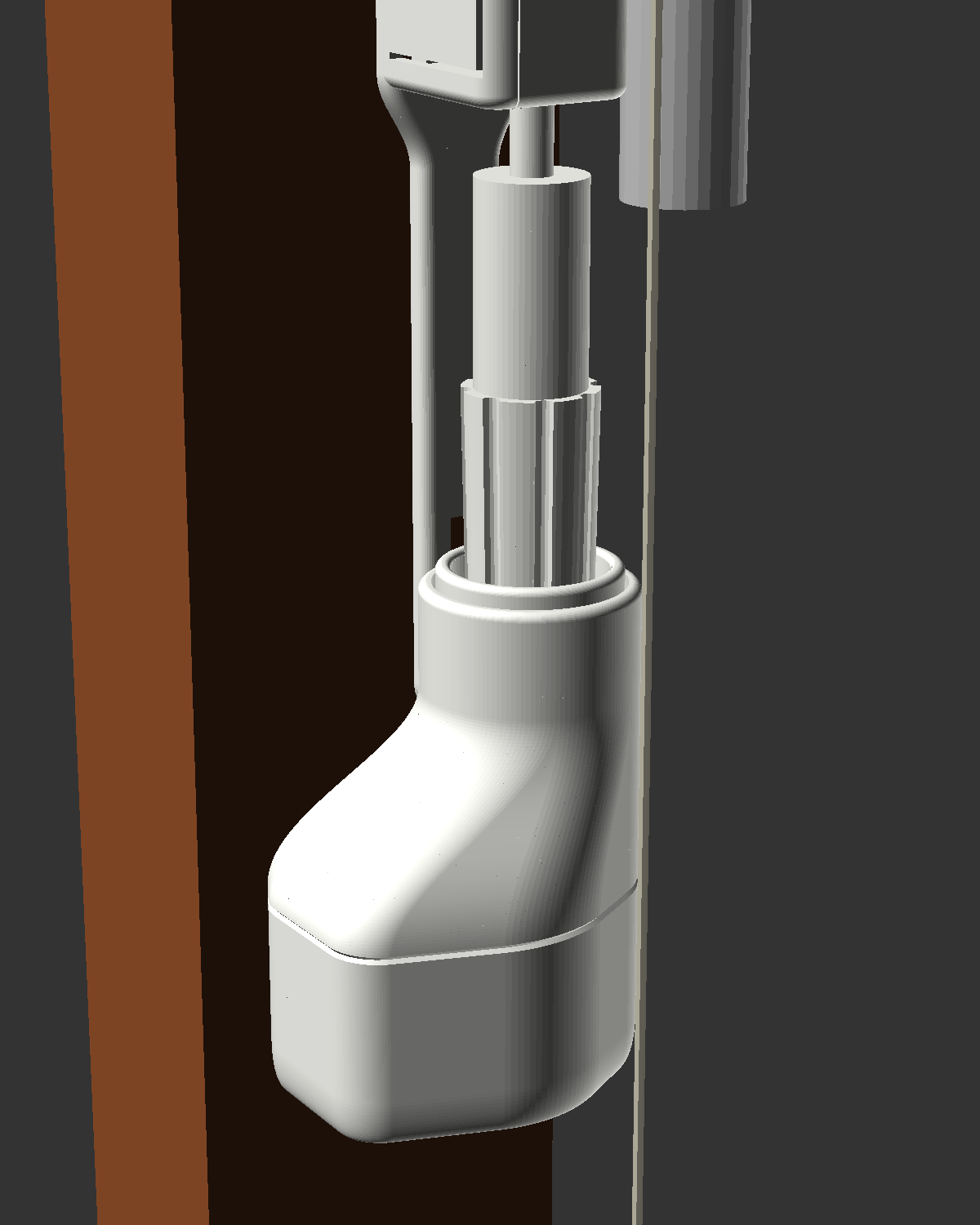
- Head = a smooth white cap that reads as an extension of the existing knob: rounded bottom, soft shoulder, tapered collar that wraps the knob's lower half, flat back against the wood. No visible screws (hidden spigot joint), no visible gears, cable leaves through the base's bottom cable exit (the old tail groove is gone with the hook tail).
- Colour: matt white PETG (or ASA) close to RAL 9010 Pure White - print a small colour
sample and hold it next to the knob in daylight (the knob may be slightly yellowed; RAL 9001/9016
are the neighbours to try). Wood-tone variant: brown/"wood" PLA or PETG, or paint matched to the
frame (
renders/visual_installed_woodtone.png,renders/photo_composite_ref3_woodtone.jpg). - Round 4 (sleek): every outside edge of the head, cup top, clip rail and controller box is a radius (no sharp
corners, no visible facets at
sleek_fn): see 4.2, 4.3 andcad/sleek.scad. Hero renders:renders/hero_head_on_knob.png,renders/hero_head_side.png,renders/visual_clip_rail_side.png,renders/ebox_sleek.png. - Controller box: same white, fully rounded shell (R6), pinhole light pipe, flush flexure button, hidden low.
- Cables: white flat cable + small white clips, or a paintable mini channel along the frame edge.
- Honest note: the current CAD shape is a first concept (offset motor body makes it slightly asymmetric). The N20 compact alternative would give the slimmest, fully coaxial "longer knob" look.
15. Risks and open questions#
| Risk / question | Impact | Mitigation |
|---|---|---|
| Knob dimensions are tape-in-photo estimates (±1-2 mm), M3/M7 not measured at all | cup too loose/tight | caliper M3/M4/M7; parametric CAD; test-print the cup first (15 min) |
| resolved 2026-10-17: hinge is above the knob, ≈ 33 mm vertical clearance | re-check with the head on (test plan step 6) | |
| Clip rail: M26/M12 are ±2 mm photo estimates; clip height above the knob has a 10-20 mm spread between photo sets; ferrule Ø / tab thickness unknown; cords' sideways offset unknown | hood too loose/tight, fork misses the key, hood brushes the cords | flexible tongues cover 11-14 mm; 24 mm fork covers -6..+12 mm; test-print the hood first and check on the window; face tab only as a last resort |
| Lift cords run against the knob - they'll rub on the collar | cord wear / noise / snag | closed smooth collar with 0.4 mm gap; check cord path M20; add a small cord guide fin if needed |
| Head weight on the thin flexible shaft + clip joint | joint strain, sagging | the clip rail takes torque only, so keep the head light (~45-60 g est.); if the joint sags, add a support ledge to the rail (not designed yet) |
| Knob axis standoff differs from 16 mm (photo est. ≈ 16, ±2 mm) | head pushes the knob out | confirm M12; the flexible shaft tolerates a few mm (est.); adjust axis_standoff |
| no hook found below the knob (2026-10-17) | rail anchors on the rod guide clip instead | |
| Clutch slip torque drift (wear, temperature) | slips during normal moves / too strong at stops | tune by test, silicone grease, replaceable O-ring; firmware current limit as 2nd layer |
| 28BYJ-48 quality varies (gear ratio, shaft play) | position drift | calibrate span; re-home periodically |
| TMC2209 VM min 4.75 V on USB 5 V | driver brown-out | short cable, no diode, measure; fallback ULN2003/DRV8833 |
| Tilt support in Google Home UI partial | poor UX in Google | use Apple/HA for tilt; test before committing |
| Firmware not compiled (esp-matter API details) | build fixes needed | README lists the assumptions |
| Left sash control location unconfirmed | cable plan | M23 |
| Solar option: winter harvest behind glass + slats is small (est. 6-17 mWh/day in Dec vs ~39 load) | battery runs flat in a dark winter | LiFePO4 buffer, low-battery policy, USB-C top-up, placement B - docs/power-solar.md §6/§8 |
| VHB on varnished wood | finish damage on removal | test on a hidden spot; prefer the clip rail |
16. Test plan#
- Measure (section 12), update parameters, rebuild STLs.
- Fit print: cup + liner only → push on/off the knob 20x; must turn the knob without slipping on the
ribs and come off with a gentle pull. Adjust
clearance,spline_h,liner_t. - Torque test (section 8) → record running/near-stop torque and turns.
- Clutch bench test: hub with O-ring in the cup, held in a vise; measure slip torque with the string/lever method; choose squeeze so slip ≈ 1.5-2x running torque.
- Motor bench test: 28BYJ-48 (bipolar mod) + TMC2209 at 5 V: rpm vs. current, noise at 30 cm, supply current with a USB meter, VM voltage under load (≥ 4.75 V).
- On-window dry run (no clip-in): hold the head on the knob, jog at
IHOMEcurrent through the full travel; check the hinge, cords, sash opening. - Calibration: guided calibration, verify span vs. M1, 20 full sweeps → re-home and compare the position error (should be ≈ 0 steps).
- End-stop safety (M1 says "closed to closed", but whether there are hard stops at both ends was not re-checked): command overtravel deliberately at
IHOME; the clutch must slip, nothing creaks; inspect the knob ribs. - Manual override: pull off/turn/push on → re-home → correct position.
- Matter: commission in one ecosystem, test open/close/50 %/stop on both endpoints, then add a second ecosystem via multi-admin; power-cycle → positions restored.
- Soak: a week of scheduled moves; check for drift, O-ring wear, clip-rail hood fit/creep, noise.
- Solar option: sleep current, move energy, a winter lux log at the panel spot - docs/power-solar.md §11.
Figures
hardware/renders/hero_head_on_knob.png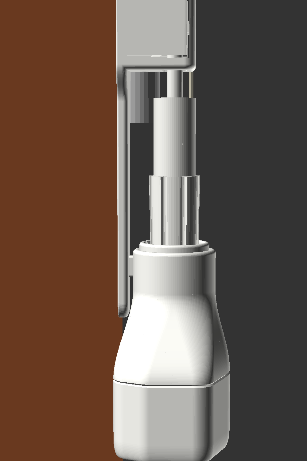
hardware/renders/hero_head_side.png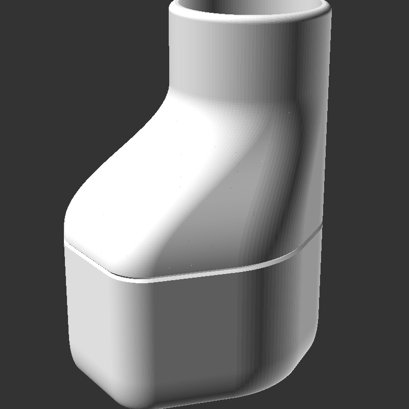
hardware/renders/housing_assembled_cutaway_free.png
hardware/renders/contact_sheet.png