Rendered from docs/ASSEMBLY.md in the repository at build time.
Estimates are labelled as such in the source; nothing on this page is a measured result unless it says so.
ValiTilt - print, assemble, install, calibrate#
Measure first (DESIGN.md §12), update the parameters at the top of the .scad files, run
tools/build_cad.sh. All settings below are typical starting points, not verified on this design.
1. Print settings#
| Part | Material | Layer | Walls / infill | Orientation / notes |
|---|---|---|---|---|
knob_cup_coupler_cup |
PETG (matt white) | 0.12-0.16 mm | 4 walls, 40 % gyroid | mouth up; floor bridges over the clutch bore - fine on most printers |
knob_cup_coupler_liner_TPU |
TPU 95A | 0.16-0.2 mm | 2 walls, 100 % | upright, slow (20-30 mm/s), no retraction tricks |
drive_hub_clutch |
PETG | 0.12 mm | 100 % | flange down; D-bore must be a snug press fit on the shaft - test print first |
housing_slim_base |
PETG or ASA (UV/heat near glass) | 0.16 mm | 3 walls, 20 % | bottom down (flat underside on the bed; no tail socket since round 5) |
housing_slim_lid |
PETG / ASA | 0.16 mm | 3 walls, 15 % | collar up, spigot down (supports under the spigot may be needed) |
anti_rotation_arm_* |
PETG | 0.2 mm | 100 % | flat |
ebox_A_usb_* / ebox_B_battery_* / ebox_C_solar_* |
PETG | 0.2 mm | 3 walls, 15 % | base bottom down; lid as exported (top on the bed): the 0.6 mm button/LED skins are the first layers |
pane_pack_panel_only |
ASA (or PETG) | 0.2 mm | 3 walls, 100 % | as exported: back down, hooks on top, no supports (with_cell: supports inside the cell pocket) |
cable_clip |
PETG | 0.2 mm | 100 % | flat side down, 10 / 6 pieces |
offset_gear_cover_base / _lid |
PETG | 0.2 mm | 3 walls | fallback drive only; tray open side up, lid as exported |
| Secondary parts | PETG | 0.2 mm | 4 walls | as convenient |
Colour: matt white close to RAL 9010 - print a 20 x 20 mm sample and compare next to the knob in daylight first. PETG with ~5 % shrink compensation is usually not needed for these sizes. Inside the window niche in summer sun, ASA tolerates heat/UV better than PETG (and much better than PLA).
2. Assembly - head (repeat for each window)#
- Motor prep: snip the two mounting ears of the 28BYJ-48 flush with tin snips (keep the can closed). Default (ULN2003A): keep the stock 5-wire motor, no bipolar mod. Cut the stock lead about 40 mm from the motor and splice it to 5 cores of the 6-wire flat cable (blue, pink, yellow, orange, red; note the core order; heat-shrink each joint, stagger the joints). Quiet TMC2209 option: bipolar mod (electronics/ELECTRONICS.md §5), 4 cores.
- Route the flat cable out through the stadium slot in the base floor (it fits the 6.8 x 2.4 mm cable flat).
- Press the motor into the base (wire box toward the glass side), add a dab of hot glue under the can if loose.
- Press the hub onto the D-shaft (support the motor; don't hammer). Fit 1 O-ring (start with one). Optional: a trace of silicone grease on the O-ring for smoother, more consistent slip.
- Push the TPU liner into the cup (keys into slots), then push the cup down over the hub/O-ring until it sits on the flange.
- Fit the lid over the cup and press its spigot into the base until flush. (A drop of CA glue only once everything is proven.)
- Anti-rotation: there is no white hook below the knob, so use the clip rail: two pieces since
2026-10-18 that snap together around the rod on the existing rod guide clip above the knob:
anti_rotation_arm_clip_rail(rail + back of the hood) andanti_rotation_arm_clip_latch(front of the hood). Two pieces because the rod runs unbroken from the clip into the knob: a one-piece part cannot get its rail behind the rod from the room side. Its clip values (DESIGN.md M26: wings 11-14 mm, 19 mm tall, ~20 mm out) are photo estimates, so print both pieces first and test them on the clip (§4 step 2): they should go on with thumb pressure and come off by hand. Do not shorten the rail yet:clip_top_above_tipinanti_rotation_arm.scadwaits for the measured clip-bottom-to-knob-tip distance (photo estimate today). The tail socket under the base was removed in round 5 (sethas_socket=trueinhousing_slim.scadonly for the old face tab / tail hook).
3. Controller box#
Default build (round 5): 2x ULN2003A. Layout keep-outs for each version are drawn in
hardware/renders/ebox_A_inside.png / ebox_C_inside.png (ebox_preview.scad, show_inside=true).
- Cut the perfboard to 57.5 x 34 mm (A) or 52 x 42 mm (B/C) and chamfer its corners 3 mm (inner box radius).
- Solder (no sockets): XIAO ESP32C6, 2x ULN2003A DIP-16 (pin 1 marks), 470 uF laid flat, tact switch where the lid plunger lands, two 5-pin JST-PH headers at the cable end. Wire per electronics/ELECTRONICS.md §0.1-§0.2 (A) or §0.1, §0.3-§0.4 (B/C). Trim all solder tails to <= 1.2 mm (B/C: Kapton tape under the board, it sits 2 mm above the cell).
- A: USB-C breakout (5k1 on CC1/CC2), PTC, 330R + 3 mm LED under the LED skin. Mount the breakout so its receptacle overhangs the perfboard edge by about 0.8 mm (it then sits close behind the box opening).
- B/C: do the 6106 safety rework first (ELECTRONICS.md §0.4: R16 -> NTC on TS, R2 -> 100k pull-down, VSYS wire to the MCP1700). Solder the 6106 flat on the perfboard by its header pins with its USB-C at the box opening; MCP1700 + 1 uF caps; 1M/1M VBAT divider + 100 nF. Tape the NTC to the cell. Check the cell's JST polarity against the 6106 before plugging in.
- C: panel lead (JST-PH 2-pin) through the third exit to the 6106 terminal block.
- Crimp a 5-pin JST-PH housing on each head cable, lay the cables into the split exits, close the lid.
- Flash the firmware (
firmware/README.md) with the ULN2003 build (3 rpm run, 2 rpm homing). - Never plug/unplug a motor while powered. Quiet option (TMC2209): see the round-4 steps in ELECTRONICS.md §1-§4 (address straps, VREF low, 100 uF at VM).
4. Installation on the window#
- Run the white flat cable: box (low, behind the curtain, near the outlet) → up the frame edge with the
printed cable clips (
cable_clip.stl, each on a 10 x 12 mm piece of the 12 mm foam tape; about every 15-20 cm, est.) → head A; second cable along the head rail to head B (left sash, confirm location). - Fit the clip rail (two printed pieces, both from the room side; no screws or glue; the rod, knob and
clip stay as they are):
a.
clip_railfirst: hold it flat on the frame face, fork end down, about 16 mm to the side of the rod away from the hinge, with its top strip just above the clip. Slide it along the frame face toward the rod: the rail passes behind the knob, the two back strips pass behind the rod just above and below the clip, and its side wall clicks onto the tab wing. Its top strip rests on the clip top. Keep a thumb on it. b.clip_latch: push it straight onto the clip from the room side, toward the frame. Its side wall clicks onto the other tab wing and its two snap tongues click into the slots ofclip_railbehind the rod. Let go: the pair must sit firm and must not slide sideways. Check the lift cords hang free beside the hood and the knob still turns by hand. Removal: pull the latch straight off toward the room, then slideclip_railsideways away from the rod. - Let the knob hang naturally. Hold the head under it with the collar key facing the frame, line up the cup and push up gently until the cup seats on the knob tip and the key slides into the rail's fork. Don't lift the knob - the shaft and the clip joint above it are fragile. The flat back should rest on the frame face. (Last resort only, if the rail can't fit: the VHB face tab - adhesive on the frame, test on a hidden spot.)
- Check: the sash opens fully without touching anything; the lift cords hang free beside the collar and are not pinched between the rail and the knob; the hinge barrel (above the knob) is clear of the rail.
5. Calibration#
- Power up → LED slow blink = not calibrated.
- Hold the box button 3-10 s → guided calibration (blind A, then B):
- turns slowly counter-clockwise (looking up at the knob from below) toward closed, slats UP → press when the slats are fully up (or it slips at the stop). This end is position 0 = home = Matter "closed".
- turns clockwise through open to closed, slats DOWN toward the room → press at the stop
- turns back → press when the slats are horizontal (expected ≈ ½ turn from the slats-up end)
- Check the log/app: span ≈ your counted turns (M1: measured ≈ 1 turn closed → open → closed, horizontal at
≈ ½ turn). Step 1 should turn counter-clockwise and step 2 clockwise, looking up at the knob from below. If a
head turns the wrong way, set
VT_DIR_INVERT_A/_B= 1 infirmware/main/app_config.h(or swap one coil pair). - Commission in your Matter app (firmware/README.md). 0 % = horizontal (open, ≈ ½ turn), 100 % = closed with
the slats UP. The slats-down position is not used by Matter (build with
VT_CLOSE_DIR_DOWN = 1if you'd rather close downward).
6. Manual override#
- Quick: pull the head straight down off the knob (the collar key slides out of the rail fork; the rail stays on the clip), turn the knob by hand, push the head back on.
- With the head on: just turn the knob - the clutch slips (feels like a soft detent).
- Afterwards hold the button 1-3 s → re-home (gentle counter-clockwise run into the slats-up stop, then back to the last position).
7. Safety notes#
- The mechanism between the panes is sealed and can't be repaired without opening the glass unit:
never raise
VT_IRUN_MA/VT_IHOME_MAor tighten the clutch beyond what the torque test showed. - If a head ever stalls or buzzes at a stop, unplug it and re-check calibration and clutch slip.
- Mains: use a certified USB charger only; everything in this pack is 5 V.
- Li-ion (versions B/C): protected cell only, the 6106 NTC rework is mandatory (no charging below 0 C), no charging in direct sun behind the glass. The cell stays in the room-side box.
- ULN2003A build: there is no driver current limit - the O-ring clutch is the only torque limit. Redo the torque/slip test (DESIGN.md §8) with the ULN build before the first unattended run.
- Keep cables away from the sash hinge and lock; don't run them through the sash gap.
- Small parts and magnets: keep away from small children.
Figures
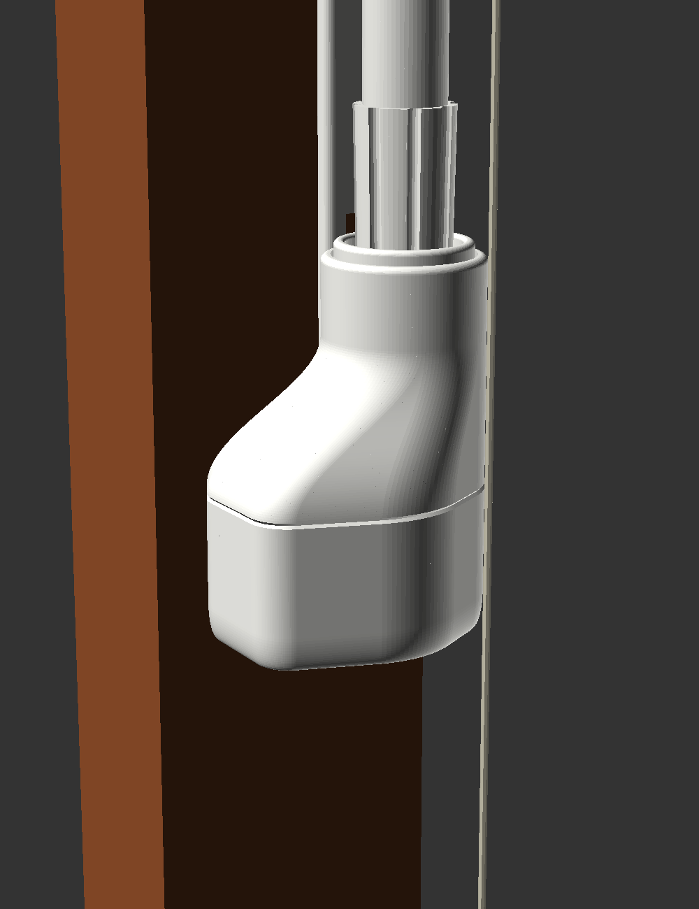
hardware/renders/visual_installed_white.png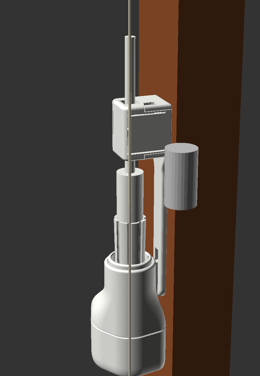
hardware/renders/visual_clip_rail_side.png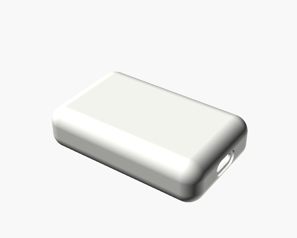
hardware/renders/ebox_A_sleek.png