Rendered from docs/power-solar.md in the repository at build time.
Estimates are labelled as such in the source; nothing on this page is a measured result unless it says so.
BlindBot / ValiTilt - battery + solar + USB-C power (v0.4 draft, 2026-10-17)#
Status: paper design. Nothing here has been built or measured. Every figure has a cited source or is
labelled (assumption) / (est.). Irradiance is PVGIS data (cited). Model: tools/power_budget.py ->
docs/power_budget.png (re-run it after you measure anything). No prices in this file (see the BOM notes).
- Part D (new, 2026-10-18, at the top) - version D: panel and a low-temperature LiPo in ONE flat pane pack, charger stays room-side; includes a correction of the 6106 TS window (about +4.6 C, not 0 C, with a 10k NTC).
- Part C (new, v0.4, at the top) - cost-down re-run: 2x ULN2003A drive at 3 / 2 rpm and a 12 V 1.5 W panel. Part C supersedes the v0.3 load and solar numbers for the default build; Part A stays valid for the quiet TMC2209 option.
- Part A (v0.3) - Li-ion/LiPo cell + small 6 V panel + USB-C through ONE charger IC, recomputed with the real move (about 1 knob turn end to end, 12 rpm = 5 s per turn, typical move about 1/2 turn = 2.5 s).
- Part B (kept, v0.2) - the LiFePO4 + BQ25570 + CN3058E design (
VT_POWER_SOLAR=1in PR "solar-power"). It is still the better choice for very dim windows, but its energy table (§B3) used an old 20 s / 3.2 mWh move and is superseded by §A2.
Part D - version D (2026-10-18): one flat pane pack with the panel AND a low-temperature cell (ESTIMATES)#
Status: paper design + CAD. Nothing in this part was built or measured. Model: python3 tools/power_budget_d.py
-> docs/power_budget_D.png. Same PVGIS hourly data (2015-2023), glass, soiling, 0.75x panel factor, sleep current
and 47.6 mWh/day load (2 blinds x 4 moves, ULN2003A) as Part C; the version C case is re-run inside the same script
as a reference and reproduces §C2 (S 89 % ... N half-shaded 13 %). Cell data are listing values, no cell
datasheet seen; every assumption is labelled.
D1. What version D is#
| Version D | |
|---|---|
| Between the panes | ONE part, pane_pack.scad variant="combined_D": the 12 V 1.5 W panel (115 x 85 x 3 mm) and, beside it, a low-temperature LiPo pouch (default: 1400 mAh, 5.3 x 47 x 52.5 mm, Grepow LT series GRP5346052) with its PCM and a 6.8k NTC on the cell |
| Pack size (CAD echo) | 139.4 x 117.8 mm; 4.1 mm over the panel, 6.6 mm over the cell (overall); hooks inside the envelope; S-curve ramp between the two zones; rounded, continuous skin |
| Pack colour | white ASA: the 0.4 mm skin over the cell is the cell's sun shield (§D5) |
| Heater | none (§D6) |
| Charger | the same Adafruit 6106 (BQ25185) in the room-side box, different rework (§D3) |
| Room-side box | ebox.scad power_variant="pack_D": board, drivers, 6106, LDO only -> 57.6 x 47.6 x 16.9 mm (B/C: 27.2 mm high) |
| Lead | about 50 cm, flat, under the gasket on the hinge side; 4 nets: PV+, BAT+, GND (panel - and cell -), NTC (§D4) |
| North / shaded option | 2200 mAh 4.6 x 52 x 82 mm LT pouch (GRP4651080): pack 144.4 x 117.8 x 5.9 mm; only where the cell stays cool in summer (listed upper limit 50 C) |
No drilling, screws or glue: the pack stands in the cavity like version C's panel pack; the cell cover (0.6 mm) drops into a rebate. A lightening bay under the same cover (below the short cell) stows the lead slack.
D2. Cell choice (listings checked 2026-10-18; values from the listing pages, not from cell datasheets)#
| Candidate | Flat size | Energy | Cold charge | Verdict |
|---|---|---|---|---|
| Grepow LT LiPo GRP5346052 | 5.3 x 47 x 52.5 mm | 1400 mAh | series page: -40..60 C, 0.2C charge at -20 C | chosen (quote / sample only, no public datasheet) |
| Grepow LT LiPo GRP4651080 | 4.6 x 52 x 82 mm | 2200 mAh | -20 C charge; listed upper limit 50 C | north / shaded windows only |
| EEMB LT LiPo series | various | - | charge only to -10 C at 0.1C | not cold enough |
| Standard thin LiPo (LP294575, 2.9 mm, 1100 mAh) | 2.9 x 45 x 75 | 1100 mAh | 0 C (and the 6106 TS window really starts at about +4.6 C, §D3) | rejected: 26-74 cold-blocked days/yr, empty on E/W/N (§D7) |
| Thin LiFePO4 (Grepow GRP4634096 1050 mAh, GRP3730048 300 mAh) | 4.4 / 3.5 mm | 3.4 / 1.0 Wh | 0 C | rejected: same cold gate, lower energy |
| LTO | smallest flat pouch about 10 Ah, 5.95 x 217 x 128 mm; small parts are 4 mAh pins | - | to -30 C | no usable flat size |
| Li-ion hybrid capacitor pouch (VINATech VPC3R8407-P, 400 F) | 3.0 mm max | about 0.2 Wh (3.65 -> 3.1 V, est.) | -25 C | rejected: 4.3 days of buffer, listed as under development (samples), RH limit, high cold ESR |
Can the BQ25185 charge LiFePO4? Yes: VSET has 3.6 V and 3.65 V settings (TI SLUSF65B, RILIM/VSET table; on the 6106 replace R19 13k with 3.6k for 3.6 V / 500 mA ILIM). LFP is not used in D because it has the same 0 C charge limit as standard LiPo; its flat cells are also smaller in energy.
D3. Charger rework and the TS window (from TI SLUSF65B; computed, not measured)#
- TS biasing: ITS 38 uA (36.5-39.5), VCOLD 1.0075 V (0.9575-1.0575), VHOT 0.115 V (0.105-0.125).
- Correction to §C2 / §A10 / ELECTRONICS.md §0.4: with the 10k B3950 NTC alone the window is +4.6 C (2.8-6.3) to 54.6 C, not 0-45 C. The cold side is conservative; the hot side is above the usual 45 C charge limit. (Version C keeps its cell room-side, so this only matters for B/C cells near a warm window.)
- Version D network (passive, no GPIO): a 6.8k NTC, TDK/EPCOS B57164K682J (K164 disc, 6.8k +-5 %, R/T curve 2903, B25/100 4200 K +-3 %; R/T table from the TDK K164 datasheet), on the cell, in parallel with 39k + 2.2k in series (41.2k) at the 6106 TS pad, R16 removed:
| NTC R25 | cold trip, nominal (TS tolerance) | hot trip, nominal (TS tolerance) |
|---|---|---|
| -5 % | -20.9 C (-17.0 .. -25.0) | 40.4 C (37.3 .. 43.8) |
| nominal | -20.1 C (-16.2 .. -24.4) | 41.7 C (38.5 .. 45.1) |
| +5 % | -19.3 C (-15.3 .. -23.7) | 42.9 C (39.6 .. 46.3) |
A 10k B3950 NTC in parallel with about 35.4k also gives -20 C, but its hot trip moves to about 52 C. Fixing that in
firmware would need two more XIAO pins, and the B/C pin map already uses all of them. The 6.8k NTC gives a
passive -20 .. +42 C window. In the PVGIS run the cell is below -16 C only about 10 h/yr (at night, when there is no
charge anyway) and below -20 C about 0.1 h/yr. So the TS tolerance costs almost nothing at the cold end. The K164 is
a lacquered disc, not a bead: its size against the 3 mm wire channel (d_ch) is not checked.
- Charge current: cut SJ1 (R1 out) and replace R20 600R with 1.2k -> ICHG about 250 mA (ICHG ~ 300 / RISET). The panel alone cannot exceed about 0.17 A. USB-C, however, would charge a cold pack cell at 1 A (0.7C), well above the listed 0.2C at -20 C. 250 mA = 0.18C for 1400 mAh.
- Unchanged from B/C: R2 removed + 100k EN pull-down; MCP1700 from VSYS; VBAT divider on GPIO2 (it now measures at the box end of the lead; the voltage drop at sleep current is negligible).
D4. Lead#
4 nets: PV+ (panel + to the 6106 VIN / terminal block), BAT+, GND (panel - and cell - joined in the pack), NTC (to TS). With a 6-way conductor, double BAT+ and GND. An assumed 0.035 x 0.7 mm FFC conductor is about 0.35 ohm per 50 cm. The about 0.23 A motor peak then gives about 0.16 V loop drop on single cores, 0.08 V doubled (estimate). Options: 6-way 1.0 mm-pitch FFC about 500 mm (part number not checked), or the BOM's 6-wire flat modular cable (2.4 mm, CCA cores; already bought for the heads). The pack's exit is an 8.0 x 2.6 mm stadium low on the cell-side edge; the box uses its existing third side exit (7.4 x 3.0 mm). Put the cell side toward the hinge.
D5. Thermal model (ASSUMPTIONS)#
T_cell = t_pack(T_out) + K_SUN x G_pack, with t_pack from §A10 (f = 0.10, about -16 C at -20 C outside) and G_pack the plane-of-array irradiance after glass, soiling and shade. K_SUN = absorptance / (about 15 W/m²K, two faces in still air): 0.06 K per W/m² for a dark skin (alpha about 0.9), 0.02 for white (alpha about 0.3). The summer peak adds cavity-air warming K_AIR = 0.02 K per W/m². Cold capacity: deliverable fraction falls linearly from 100 % at +20 C to G20 at -20 C (LT cell 0.90, standard LiPo 0.70, LFP 0.65: assumptions); the rest is "trapped", not lost.
Summer peak cell temperature (est.):
| Skin | South | East | West | North |
|---|---|---|---|---|
| dark | 78 C (260 h/yr > 60 C) | 77 C | 82 C | 44 C |
| white | 53 C (59 h > 45 C) | 50 C (22 h) | 55 C (76 h) | 35 C |
White keeps the LT cell inside its listed -40..60 C and the charger stops charging above about 42 C. The 2200 mAh option (listed to 50 C) fits north windows only. Long hours above 45 C still speed up calendar ageing (not quantified).
D6. Heater from the panel, gated by the NTC (checked, rejected)#
A resistor heater fed from the panel only when the cell is below the charge limit. December, standard 0 C LiPo, dark skin: it uses 21-34 mWh/day of panel output on S/E/W/N, and the lowest charge changes S 50 -> 50 %, E 7 -> 15 %, W/N still empty. The cell area loses about 40 mW/K, so a 16 K lift needs about 0.65 W continuous. At 300 W/m² the panel delivers about 0.34 W electrical, while the same sun falling on the cell area already puts about 0.9 W into it as heat. Verdict: no heater. A cold-rated cell does the job without one.
D7. Winter budget (47.6 mWh/day, PVGIS 2015-2023, ESTIMATES)#
December mean net vs load and the lowest reachable charge over 9 years (charge that can be used at the cell's temperature at that hour):
| Window | Dec net (D default) | D: 1400 mAh LT, white | D north option: 2200 mAh LT | C reference: 2000 mAh room-side | standard 1100 mAh LiPo in the pack, dark skin |
|---|---|---|---|---|---|
| South | +153 mWh/day | 78 % | 82 % | 89 % | 50 % (26 cold-blocked days/yr) |
| East | -11 | 62 % | 72 % | 77 % | 7 % |
| West | -20 | 36 % | 55 % | 59 % | empty 1.5 d/yr |
| North | -40 | 16 % | 41 % | 45 % | empty 42 d/yr |
| North, half-shaded | -46 | empty about 21 d/yr | 13 % | 13 % | empty 76 d/yr |
LT cells: 0 cold charge-inhibit days with the -20 C trip (white skin), and no hot-inhibit days that cost charge.
Lowest reachable charge by month (%, ESTIMATES):
| Case | Jan | Feb | Mar | Apr | May | Jun | Jul | Aug | Sep | Oct | Nov | Dec |
|---|---|---|---|---|---|---|---|---|---|---|---|---|
| D 1400 mAh, south | 87 | 89 | 90 | 92 | 94 | 96 | 97 | 97 | 95 | 93 | 85 | 78 |
| D 1400 mAh, north | 19 | 16 | 31 | 92 | 94 | 96 | 97 | 97 | 95 | 93 | 74 | 42 |
| D 1400 mAh, north half-shaded | 0 | 0 | 0 | 23 | 94 | 96 | 97 | 97 | 95 | 83 | 54 | 21 |
| D 2200 mAh, north half-shaded | 25 | 13 | 13 | 31 | 88 | 96 | 97 | 97 | 95 | 87 | 68 | 45 |
| C 2000 mAh room-side, north half-shaded | 23 | 14 | 13 | 30 | 93 | 100 | 100 | 99 | 99 | 90 | 71 | 46 |
Plot: docs/power_budget_D.png. As in Part C, the 0.75x panel factor is the weakest input. The cold-capacity
factor of the LT cell is the next one.
D8. Versions compared#
| A: USB-C | B: battery + USB-C | C: battery + panel | D: combined pane pack | |
|---|---|---|---|---|
| Room-side box | 63.1 x 39.6 x 16.7 mm | 57.6 x 47.6 x 27.2 mm | 57.6 x 47.6 x 27.2 mm | 57.6 x 47.6 x 16.9 mm |
| Between the panes | nothing | nothing | panel pack 87.8 x 117.8 x 3.7 mm (4.1 at hooks), no cell | one pack 139.4 x 117.8 mm, 4.1 / 6.6 mm, panel + cell (north: 5.9 mm) |
| Lead through the gasket | none (USB cable) | none | 2 cores | 4 nets (6-way flat) |
| Cell temperature | - | room | room | cavity: about -20 .. +55 C (est.) |
| Cold risk | none | none | none | charging relies on the LT cell's -20 C rating + the TS window; capacity loss in frost (est.) |
| Heat risk | none | none | panel only | cell behind glass in summer: white pack required |
| Winter (2 x 4 moves) | mains | about 122 days per charge | S 89 % ... N half-shaded 13 % | S 78 % ... N half-shaded empty about 21 d/yr (2200 mAh option: 13 %) |
| Cycle use | - | about 3 USB recharges/yr | about 2.4 full-equivalent cycles/yr (shallow daily) | about 3.4 full-equivalent cycles/yr; cycle life of the LT cell not published |
| Complexity | lowest | 6106 rework | rework + panel pack + lead | special-order cell, different NTC network + ISET rework, 4-net lead, cell in a part that is hard to reach |
D9. Not verified (open)#
- LT cell: no datasheet; -20 C charge rate, 60 / 50 C upper limits, cycle life, cold capacity (G20 = 0.9 assumed), PCM temperature rating and the pouch's real thickness/swelling are from the series pages or assumed. Order samples.
- The TS window is computed from TI's thresholds and TDK's R/T table, not measured: bench-test it in a freezer and an oven. The NTC disc size against the 3 mm channel is not checked.
- Pack temperatures (K_SUN, K_AIR, f): log a dummy pack with a thermometer for a cold week and a sunny week.
- FFC part number, conductor size and whether it survives the gasket; the cable choice under the gasket.
- Panel output (0.75x factor) and the panel pad position, as in Part C.
- Fit in the cavity: the gap and the slat clearance are not measured (same as version C).
- Weekly re-home assumes the open-loop position drift over a week stays small; not tested.
D10. Dark winters: panel factor, weekly re-home and a low-battery mode (ESTIMATES)#
Model: python3 tools/power_modes.py (same PVGIS data, glass, cells, cell temperatures and charge windows as
§C2 and §D7; the pack sits on the outer pane in front of the slats, so closed slats do not shade it). Conservative
sensitivity on the panel: F = effective panel current / P124 current = 0.75 (current model), 0.375 and 0.19,
standing in for darker winters, snow and dirt on the glass and the unknown low-light behaviour of the 12 V panel.
Loads (recomputed): one 1/2-turn move 2.42 mWh, one re-home 6.99 mWh, sleep 14.27 mWh/day.
| 2 blinds | daily re-home | weekly re-home | saved | low-battery day (1 move per blind, no re-home) |
|---|---|---|---|---|
| 4 moves/day | 47.6 mWh/day | 35.6 | 12.0 | 19.1 |
| 8 moves/day | 66.9 mWh/day | 55.0 | 12.0 | 19.1 |
Low-battery mode (design): at midnight, if the reachable charge is below 20 %, each blind makes only one move that day and skips the re-home; the mode ends at 30 %. Button presses always run (not counted in the model).
Each cell: lowest reachable charge 2015-2023 for daily re-home / weekly re-home / weekly + low-battery mode, or empty N d = days per year with no reachable charge; "(low-battery mode N d)" = days per year spent in it.
2 blinds x 4 moves/day (daily re-home / weekly re-home / weekly + low-battery mode):
| Version | F | South | East | West | North | North, half-shaded |
|---|---|---|---|---|---|---|
| C 2000 mAh room-side | 0.75 | 89% / 93% / 93% | 77% / 83% / 83% | 59% / 75% / 75% | 45% / 62% / 62% | 13% / 39% / 39% |
| C 2000 mAh room-side | 0.375 | 81% / 86% / 86% | 51% / 70% / 70% | 41% / 57% / 57% | 13% / 39% / 39% | empty 33 d / 6% / 16% (low-battery mode 53d) |
| C 2000 mAh room-side | 0.19 | 76% / 83% / 83% | 26% / 49% / 49% | 19% / 44% / 44% | empty 32 d / 7% / 16% (low-battery mode 51d) | empty 246 d / empty 192 d / empty 133 d (low-battery mode 255d) |
| D 1400 mAh LT | 0.75 | 78% / 85% / 85% | 62% / 72% / 72% | 36% / 59% / 59% | 16% / 41% / 41% | empty 21 d / 9% / 14% (low-battery mode 31d) |
| D 1400 mAh LT | 0.375 | 66% / 74% / 74% | 28% / 53% / 53% | 10% / 33% / 33% | empty 21 d / 9% / 14% (low-battery mode 31d) | empty 73 d / empty 34 d / empty 6 d (low-battery mode 105d) |
| D 1400 mAh LT | 0.19 | 60% / 69% / 69% | empty 2 d / 22% / 22% | empty 10 d / 16% / 17% (low-battery mode 7d) | empty 71 d / empty 33 d / empty 5 d (low-battery mode 104d) | empty 240 d / empty 184 d / empty 136 d (low-battery mode 229d) |
| D 2200 mAh LT ¹ | 0.75 | 82% / 87% / 87% | 72% / 79% / 79% | 55% / 69% / 69% | 41% / 57% / 57% | 13% / 36% / 36% |
| D 2200 mAh LT ¹ | 0.375 | 75% / 80% / 80% | 50% / 65% / 65% | 38% / 53% / 53% | 13% / 36% / 36% | empty 29 d / 8% / 15% (low-battery mode 51d) |
| D 2200 mAh LT ¹ | 0.19 | 70% / 77% / 77% | 24% / 45% / 45% | 19% / 41% / 41% | empty 28 d / 9% / 15% (low-battery mode 48d) | empty 248 d / empty 195 d / empty 136 d (low-battery mode 260d) |
2 blinds x 8 moves/day (daily re-home / weekly re-home / weekly + low-battery mode):
| Version | F | South | East | West | North | North, half-shaded |
|---|---|---|---|---|---|---|
| C 2000 mAh room-side | 0.75 | 80% / 86% / 86% | 58% / 71% / 71% | 34% / 49% / 49% | 11% / 33% / 33% | empty 28 d / empty 2 d / 15% (low-battery mode 50d) |
| C 2000 mAh room-side | 0.375 | 71% / 77% / 77% | 21% / 40% / 40% | 12% / 31% / 31% | empty 28 d / empty 2 d / 15% (low-battery mode 50d) | empty 87 d / empty 57 d / empty 4 d (low-battery mode 125d) |
| C 2000 mAh room-side | 0.19 | 54% / 69% / 69% | empty 7 d / 12% / 17% (low-battery mode 11d) | empty 17 d / 2% / 16% (low-battery mode 32d) | empty 86 d / empty 55 d / empty 2 d (low-battery mode 123d) | empty 292 d / empty 267 d / empty 163 d (low-battery mode 301d) |
| D 1400 mAh LT | 0.75 | 65% / 73% / 73% | 35% / 53% / 53% | 0% / 22% / 22% | empty 15 d / 0% / 14% (low-battery mode 26d) | empty 58 d / empty 37 d / empty <1 d (low-battery mode 83d) |
| D 1400 mAh LT | 0.375 | 52% / 60% / 60% | empty 4 d / 12% / 17% (low-battery mode 4d) | empty 14 d / empty <1 d / 12% (low-battery mode 23d) | empty 58 d / empty 37 d / empty <1 d (low-battery mode 83d) | empty 119 d / empty 92 d / empty 51 d (low-battery mode 142d) |
| D 1400 mAh LT | 0.19 | 31% / 49% / 49% | empty 36 d / empty 15 d / 3% (low-battery mode 53d) | empty 47 d / empty 26 d / 0% (low-battery mode 66d) | empty 117 d / empty 90 d / empty 49 d (low-battery mode 141d) | empty 288 d / empty 262 d / empty 175 d (low-battery mode 283d) |
| D 2200 mAh LT ¹ | 0.75 | 74% / 79% / 79% | 54% / 65% / 65% | 31% / 46% / 46% | 13% / 31% / 31% | empty 26 d / empty <1 d / 13% (low-battery mode 48d) |
| D 2200 mAh LT ¹ | 0.375 | 66% / 71% / 71% | 21% / 39% / 39% | 12% / 29% / 29% | empty 26 d / empty <1 d / 13% (low-battery mode 48d) | empty 83 d / empty 53 d / empty 1 d (low-battery mode 123d) |
| D 2200 mAh LT ¹ | 0.19 | 51% / 63% / 63% | empty 4 d / 11% / 14% (low-battery mode 10d) | empty 13 d / 4% / 14% (low-battery mode 30d) | empty 82 d / empty 52 d / empty 1 d (low-battery mode 122d) | empty 294 d / empty 269 d / empty 169 d (low-battery mode 302d) |
¹ The 2200 mAh cell's listed upper limit is 50 C; the estimated summer peak is about 53 / 50 / 55 C on south / east / west windows (§D5). Use it on north windows only. Its south/east/west rows are for comparison.
Does the low-battery mode keep every window off empty? No. With weekly re-home it closes the gap wherever the deficit is short:
- At F 0.75 every case stays above zero at 4 moves. At 8 moves only D 1400 mAh on a half-shaded north window is left (under a day a year).
- At F 0.375 it fixes all of C and D 2200 mAh at 4 moves, and all of C at 8 moves except half-shaded north (4 d/yr). D 1400 mAh still runs empty on half-shaded north windows (6 d/yr at 4 moves).
- At F 0.19 north windows need C or D 2200 mAh plus the mode. Half-shaded north windows run empty 133-175 days a year in every version: even the 19 mWh/day low-battery load (three quarters of it is sleep) exceeds what the panel makes there for most of the year.
Recommendation (estimates):
| Window | Version | Why |
|---|---|---|
| South | C or D 1400 mAh | above about 30 % in every case, even F 0.19 at 8 moves |
| East / West | C, or D 1400 mAh with weekly re-home | D 1400 mAh runs empty at F 0.19 with daily re-home; at 8 moves it needs weekly re-home + low-battery mode and still falls to about 0-3 % at F 0.19 (C: 16-17 %) |
| North | C or D 2200 mAh, weekly re-home + low-battery mode | stays above about 13-16 % down to F 0.19 at 4 moves and to F 0.375 at 8 moves; D 1400 mAh runs empty at F 0.19 |
| North, half-shaded | A (USB-C), or C/D with a planned USB-C top-up in mid-winter | no panel version holds through a dark winter at F 0.19 |
Default settings for B/C/D builds: weekly re-home (7 days), plus a re-home after any power loss, missed
step or manual override. Low-battery mode on (20 % enter / 30 % exit), reporting Matter BatChargeLevel = Warning
so the user is told to top up over USB-C. Daily re-home only where position accuracy matters more than winter
reserve. Firmware switches VT_REHOME_DAYS, VT_SOC_LOWBATT_ENTER / EXIT and VT_POWER_MODES match these
numbers. Weekly re-home still assumes the open-loop drift over a week stays small; that is not bench-tested.
Part C - v0.4 cost-down re-run (round 5, 2026-10-17): ULN2003A drive + 12 V 1.5 W panel (ESTIMATES)#
All numbers in this part are model estimates (python3 tools/power_budget.py; v0.3 comparison with
--v03). Nothing was measured. Same PVGIS data, glass, shading, sleep and cell assumptions as Part A.
What changed against v0.3:
| Input | v0.3 (Part A) | v0.4 (this part) | Source / label |
|---|---|---|---|
| Driver | 2x TMC2209, current-limited | 2x ULN2003A, full current half-step | design decision |
| Motor power while moving | 0.50 W (upper bound) | 0.64 W (4.95 V x ~130 mA avg) | ESTIMATE from the 50 ohm/half-coil datasheet value |
| Homing power | 0.30 W | 0.64 W (no current reduction on a ULN) | ESTIMATE |
| Run / homing speed | 12 / 6 rpm | 3 / 2 rpm (pull-in limit, review M1) | firmware setting |
| Daily re-home | 1/2 turn @6 rpm + 1 s, back @12 | (1/2 + 0.165) turn @2 rpm, back 1/2 turn @3 rpm | ASSUMPTION (overtravel) |
| 3.3 V LDO Iq | 0.025 uA | 1.6 uA (MCP1700) | Microchip datasheet |
| Panel | 6 V P124 66 x 113 mm, Imp 0.220 A | 12 V 1.5 W 115 x 85 x 3 mm, effective 0.165 A at 1000 W/m2 | listing size; current = 0.75 x P124, ESTIMATE |
C1. Move energy and daily load (2000 mAh LiPo, Thread sleepy device 150 uA)#
| v0.3 TMC2209 | v0.4 ULN2003A | |
|---|---|---|
| 1/2-turn move | 0.58 mWh (2.5 s) | 2.42 mWh (10 s) |
| daily re-home | 1.31 mWh | 6.99 mWh |
| load, 2 blinds x 4 moves/day | 21.4 mWh/day | 47.6 mWh/day |
| load, 2 blinds x 8 moves/day | 26.0 mWh/day | 66.9 mWh/day |
| battery-only life, 2 x 4 moves | about 247 days | about 122 days |
| battery-only life, 2 x 8 moves | about 209 days | about 88 days |
| battery-only life, 1 blind x 4 moves | about 287 days | about 179 days |
The ULN build roughly halves battery-only life (version B). The cause is the 4x longer move at 3 rpm at full coil current, and the daily re-home at 2 rpm (about 30 % of the daily load is sleep, the rest is motion). If the coils really are 200 ohm (the motor listing's value) the motor power is about 0.16 W and the 2 x 4 load is about 26.0 mWh/day -> about 209 days. Measure one coil before trusting either figure. Levers if B is too short: re-home weekly instead of daily (saves about 12 mWh/day for 2 blinds), fewer moves, or the quiet TMC2209 option.
C2. Solar balance, version C (panel inter-pane on the outer pane = placement B, 2 x 4 moves, 47.6 mWh/day)#
December mean harvest into the cell minus load, and the lowest charge over 2015-2023 (PVGIS hourly):
| Facade | Dec net, no shade | minimum charge | Dec net, half shaded | minimum charge | empty days/yr |
|---|---|---|---|---|---|
| South | +153 mWh/day | 89 % | +50 | 81 % | 0 |
| East | -11 | 77 % | -32 | 51 % | 0 |
| West | -20 | 59 % | -36 | 41 % | 0 |
| North | -40 | 45 % | -46 | 13 % | 0 |
- v0.3 (P124 + TMC2209) for comparison: South +248 mWh/day / 97 %, North 86 % unshaded.
- At 2 x 8 moves (66.9 mWh/day) half-shaded North runs empty about 28 days a year; East/West stay above 12 %.
- Room-side panel placement (behind the slats) is much weaker: South 77 %, East 29 %, West 23 %, North empty about 25 days/yr at 2 x 4 moves. Keep the panel between the panes.
- June surplus is large everywhere (about +0.8 to +1.7 Wh/day), so the cell refills over the summer; the risk is the December-January deficit on East/West/North windows.
- Cold: the charger only charges above about +4.6 C (NTC on TS after the 6106 rework, ELECTRONICS.md §0.4; "0 C" in older text - see §D3). The cell stays in the room-side box, so the 0 C gate does not block winter charging.
Plot: docs/power_budget.png (v0.4). The 0.75x panel factor is the weakest number here: log one week of
charge current on a south window before relying on the December figures.
C3. Fit (from the CAD echoes)#
| Part | Outer size | Notes |
|---|---|---|
Controller box A (ebox.scad, usb) |
63.1 x 39.6 x 16.7 mm | was 61.6 x 37.6 x 23.6 |
Controller box B / C (battery / solar, cell under the board) |
57.6 x 47.6 x 27.2 mm | was 65.6 x 47.6 x 34.6 |
Box B / C, cell_layout="beside" |
111.6 x 47.6 x 16.9 mm | flattest, longer |
Pane pack panel_only (12 V panel) |
87.8 x 117.8 mm, 3.7 mm (4.1 at the hooks) | was 68.8 x 115.8 x 3.3 |
Pane pack with_cell |
134.4 x 117.8 mm, 4.2 mm | cell inter-pane only if needed |
Heights inside the box use two ASSUMED component heights (terminal block 8.5 mm, mated JST-PH + wire bend
10 mm): tb_h and jst_h in ebox.scad.
Part A - v0.3 Li-ion + 6 V panel + TMC2209 (quiet option)#
A0. Summary (v0.3)#
| Result (ESTIMATES unless cited) | |
|---|---|
| Move energy | about 0.6 mWh per 1/2-turn move, about 1.0 mWh per full turn, about 1.3 mWh per daily re-home (§A2) |
| Daily load, 1 controller, 2 blinds, Thread SED 150 µA | about 21 mWh/day at 4 moves/blind/day, about 26 mWh/day at 8 (sleep is two thirds of it: 14 mWh/day) |
| Battery only (no sun, no USB), LiPo 2000 mAh | about 250 days at 4 moves, about 210 days at 8 (1 blind: about 290). Pessimistic 250 µA SED, 8 moves: about 160 days. Wi-Fi instead of Thread (DTIM3): about 140 days |
| Solar, December, recommended charger, one 66 x 113 mm 6 V panel | inter-pane (outside the slats), south: about +248 mWh/day net; east/west: +18 to +30; north: about -9. Room side (behind the slats): south +49, east/west -11 to -14, north -21 |
| Solar, June | +94 to +2 311 mWh/day net in every case - the cell is full within a day or two |
| Year-round, 2014-2023 hourly simulation (cell room-side) | cell never empties in any case modelled (min charge 97 % inter-pane south; 22 % worst case = room side, north, shaded, 8 moves). USB-C is a convenience, not a necessity, except in the worst case |
| Flat inter-pane pack (§A10) | panel-only pack 3.3 mm thick (3.7 mm at 4 snap hooks), 68.8 x 115.8 mm - RECOMMENDED, cell stays warm in the room-side box. Pack with the cell side by side: 4.2 mm (4.6 at hooks), 115.4 x 115.8 mm, 1100 mAh 2.9 mm pouch; stacked would be 6.9 mm |
| Cold (§A10) | design minimum -20 C outdoors -> inter-pane pack about -16 C (range -18 to -10 C, labelled assumption). A Li-ion/LiPo cell must not charge below 0 C, so a cell in the pack charges only on mild winter days: it still never empties (min 34-81 % inter-pane, 2 x 8 moves) but has 2x less buffer. LTO / hybrid caps: no flat part of a usable size found |
| Recommended cell | 1S LiPo 3.7 V 2000 mAh, 50 x 40 x 8 mm, with protection PCB, JST-PH in the room-side controller box (never in the sun, never below 0 C while charging). If it must live in the flat inter-pane pack: a 2.9 mm 1100 mAh pouch (pack 4.2 mm) or the -20 C-rated 4 mm 1000 mAh 404060 (pack 5.3 mm) |
| Recommended panel | 6 V monocrystalline, about 1.2-1.35 W, 66 x 113 x 2.6 mm (Voltaic P124 class), inter-pane on the outer pane (placement B) where the slats can't shade it |
| Recommended charger (solar AND USB-C in one IC) | TI BQ25185 linear charger with power path and battery-tracking VINDPM; module: Adafruit 6092 (BQ25185 + USB-C, 30.2 x 19.0 x 10.0 mm). Alternative: TI bq24074 / Adafruit 4755 (fits less well, 1.1 mA input quiescent, needs a >= 6 V panel) |
| Fit in the sleek shell | yes, in the power_variant="liion_solar" controller box (cad/ebox.scad): 65.6 x 47.6 x 34.6 mm outer (usb-only box: 61.6 x 37.6 x 23.6). Head housing unchanged (no battery in the head) |
A1. Architecture (v0.3)#
 6 V panel (inter-pane) --VIN--+                     +--SYS (3.0-4.5 V)--> TPS7A02 3.3 V LDO --> XIAO ESP32-C6 3V3
                               |   BQ25185           |                 \-> TPS61023 boost 5 V (EN) --> 2x TMC2209 VM (gated)
 USB-C 5 V (CC 5.1k) ---VIN----+   (power path)  ----+
                                       |BAT
                                 1S LiPo 2000 mAh (+PCM), NTC on TS (0-45 C charge window)
- One input, two sources. The BQ25185 has a single VIN. Panel and USB-C 5 V are joined through two Schottky (or ideal) diodes so neither back-feeds the other (assumption: diode drop is negligible against the VBAT + 330 mV VINDPM point; with USB-C the panel diode simply blocks). The Adafruit 6092 board already has the USB-C (5.1 k CC) and separate VIN pads.
- Why BQ25185. From the TI datasheet (SLUSF65B, https://www.ti.com/lit/ds/symlink/bq25185.pdf): input 3.0-18 V (25 V tolerant), up to 1 A charge, power path with SYS regulated at 4.5 V, battery-tracking VINDPM = VBAT + 330 mV (lets a weak panel sit near its maximum-power point without collapsing), IQ_IN 0.75 mA typ / 1 mA max while the input is valid, IQ_BAT 4 µA typ / 5 µA max in battery-only mode, 30 µA sleep input current, TS thermistor input, 6 h safety timer.
- Why not the boost-converter harvester here. The BQ25570 (Part B) needs about 0.5 µA and real MPPT, so it harvests far better in dim light (see §A5 table: north/room-side cases), but it can't take USB-C 5 V directly as a fast charger. Use Part B when the panel can only go room-side on a north window.
- Sleep rail. TPS7A02 (TI, https://www.ti.com/lit/ds/symlink/tps7a02.pdf): 25 nA Iq, 200 mA, dropout <= 270 mV at 200 mA (85 C). Below about 3.5 V cell it runs in dropout and the ESP32-C6 (3.0-3.6 V) follows the cell. Do not use the Adafruit 6092's on-board 3.3 V buck for the sleep rail: Adafruit names it TPS62569; the similar TI TLV62569 has 35 µA operating Iq (TI datasheet), which would add about a quarter to the sleep load. Hold its EN pad low, and remove or cut the always-on green 3.3 V LED.
- Motor rail as in Part B: TPS61023 boost (0.1 µA shutdown, TI) enabled only while moving; TMC2209 VIO also gated, because an idle TMC2209 draws mA-level supply current.
A2. Move energy, from the real move (ESTIMATES with cited inputs)#
| Input | Value | Source |
|---|---|---|
| Travel | about 1 knob turn end to end; typical move about 1/2 turn | measurement M1 (2026-10-17) |
| Speed | 12 rpm (VT_RUN_RPM) = 5.0 s per turn; 1/2 turn = 2.5 s; homing at 6 rpm |
firmware app_config.h |
| Motor coil | 28BYJ-48 5 V, 50 Ω per half coil (±7 %) -> 100 Ω per bipolar series coil -> at most 5 V / 100 Ω = 50 mA per phase -> <= 0.50 W from the 5 V rail with both phases on (used as the bound, including TMC2209 quiescent) | Mikroe 28BYJ-48 datasheet, https://download.mikroe.com/documents/datasheets/step-motor-5v-28byj48-datasheet.pdf |
| Homing current | 35 mA rms (VT_IHOME_MA) -> about 0.30 W |
firmware + Ohm's law (assumption: +0.05 W driver) |
| Boost efficiency | 0.88 at 3.0-4.2 V -> 5 V, about 100 mA | (assumption, read from TI TPS61023 efficiency curve) |
| MCU awake during a move | 0.10 W for motor time + 2 s | (assumption) |
| Ramps + rail enable | +0.3 s per move (2 x 400 µsteps of 16 300 per turn is about 0.1 s) | firmware + (assumption) |
Result (tools/power_budget.py): 1/4 turn 0.34 mWh, 1/2 turn 0.58 mWh, 1 turn 1.04 mWh; daily re-home
(1/2 turn to the CCW stop at 6 rpm + 1 s slip, then back at 12 rpm) 1.31 mWh per blind. The old v0.2 figure
(3.2 mWh per 20 s move) assumed about 4 turns of travel; the measured 1-turn span cuts the move energy by about 5x.
A3. Sleep current and daily load#
| Item | µA from the cell | Source |
|---|---|---|
| ESP32-C6 Matter-over-Thread sleepy end device (ICD), average | 150 design (125-231 measured by others; 250 pessimistic) | tomasmcguinness.com 2025-01-06 (XIAO ESP32C6 icd_app, 231 µA); github.com/vavallee/homecadia (125 µA) |
| BQ25185 battery-only quiescent | 4.0 typ (5 max) | TI SLUSF65B |
| TPS7A02 Iq | 0.025 | TI TPS7A02 datasheet |
| TPS61023 shutdown | 0.1 | TI TPS61023 datasheet |
| VBAT divider 1 M + 1 M at about 4 V | 2.0 | Ohm's law |
| Cell protection PCB | 3 | (assumption, DW01-class) |
| Self-discharge | 2 %/month | (assumption, typical Li-ion at room temperature) |
| Wi-Fi alternative (no Thread) | 368 at DTIM 3, 919 at DTIM 1 (auto light sleep, average) | Espressif "Low Power Mode in Wi-Fi Scenarios", ESP32-C6, https://docs.espressif.com/projects/esp-idf/en/stable/esp32c6/api-guides/low-power-mode/low-power-mode-wifi.html (dev-board measurement, not Matter-specific) |
Energy is counted at the 3.7 V nominal cell voltage (the LDO passes current 1:1).
| Case (1 controller) | Load mWh/day | Battery-only days, LiPo 2000 mAh | 1200 mAh LiPo | 18650 3000 mAh |
|---|---|---|---|---|
| Thread 150 µA, 2 blinds x 4 moves | 21.4 | 247 | 158 | 342 |
| Thread 150 µA, 2 blinds x 8 moves | 26.0 | 209 | 133 | 293 |
| Thread 150 µA, 1 blind x 4 moves | 17.7 | 287 | 187 | 394 |
| Thread 250 µA (pessimistic), 2 x 8 | 34.8 | 161 | 101 | 230 |
| Wi-Fi DTIM 3, 2 x 4 | 40.7 | 140 | 87 | 201 |
| Nordic-class Matter window covering, 33 µA (nRF52840, 500 ms poll; §A11), 2 x 4 | 11.0 | 417 | 281 | 549 |
| Wi-Fi DTIM 1, 2 x 4 | 89.6 | 67 | 41 | 98 |
Usable capacity = 85 % of nominal (cell to about 3.5 V under load) (assumption); days include self-discharge. Moves/day assumption: 4 (open in the morning, two adjustments, close at night) and 8 (automations).
A4. Light at the panel - sources and through-glass losses#
- Irradiance: PVGIS v5.3 (EU JRC), PVGIS-SARAH3 + ERA5, hourly 2014-2023, generic grid
point in southern Finland, about 60 N (not a specific address; the exact query point is
LAT, LONintools/power_budget.py), vertical plane, DEM horizon:https://re.jrc.ec.europa.eu/api/v5_3/seriescalc?lat=<LAT>&lon=<LON>&angle=90&aspect=<0|-90|90|180>&startyear=2014&endyear=2023&outputformat=json(aspect 0 = S, -90 = E, 90 = W, 180 = N). Monthly means of G(i) on the outside of the glass, kWh/m²/day:
| Facing | Jan | Feb | Mar | Apr | May | Jun | Jul | Aug | Sep | Oct | Nov | Dec |
|---|---|---|---|---|---|---|---|---|---|---|---|---|
| S | 0.67 | 1.69 | 2.98 | 3.69 | 3.81 | 3.65 | 3.51 | 3.40 | 2.78 | 1.71 | 0.56 | 0.43 |
| E | 0.18 | 0.63 | 1.55 | 2.60 | 3.30 | 3.60 | 3.19 | 2.59 | 1.66 | 0.78 | 0.20 | 0.10 |
| W | 0.14 | 0.55 | 1.45 | 2.51 | 3.34 | 3.58 | 3.35 | 2.69 | 1.67 | 0.73 | 0.18 | 0.08 |
| N | 0.07 | 0.21 | 0.50 | 0.87 | 1.39 | 1.76 | 1.60 | 1.06 | 0.65 | 0.29 | 0.09 | 0.04 |
For contrast, northern Finland (PVGIS PVcalc 65.0 N 25.5 E, vertical, 2005-2023 monthly H(i)_d): south December 0.03, June 3.67 kWh/m²/day - in the north the battery alone has to carry about Nov-Jan.
- PVGIS knows terrain only, not buildings or trees: a "shaded" case multiplies irradiance by 0.5 (assumption).
- Glass (EN 410 direct solar transmittance ST, Pilkington Glasfakta 2024, https://www.pilkington.com/-/media/2ace97721b82435f8a0f32d606639783.pdf): 4 mm clear float 0.86 (6 mm: 0.83); double unit 6-16Ar-4 with one Optitherm S3 low-E 0.55 (clear double unit 0.76). ST is the conservative metric for c-Si (light transmittance is 0.91 / 0.81). v0.3 first used 0.88, which is the g-value (includes re-radiated heat) - corrected. Typical Finnish MSE window: single outer pane, double unit in the inner sash, blind between (Solar Kaihdin MSE guide https://solar.fi/wp-content/uploads/2022/04/mitoitus-mse.pdf; Safetyset https://www.safetyset.fi/artikkelit/ikkunarakenteet) - so an inter-pane panel looks out through one pane. Dust and incidence angle: x0.95 (assumption; PVGIS quotes 2-4 % AOI loss for a bare module).
- Placement B, inter-pane (on the inner face of the outer pane, outside the slats): T = 0.86 x 0.95 = 0.82.
- Placement A, room side (on the inner pane, light passes the slats): T = 0.86 x 0.55 x 0.5 (slats mostly horizontal by day, assumption) x 0.95 = 0.22.
- Panel: Voltaic P124, 6 V, 66 x 113 x 2.6 mm, Voc 7.28 V, Vmp 6.23 V, Imp 220 mA, 1.35 W peak (Voltaic data, https://voltaicsystems.com/1-watt-6-volt-solar-panel-etfe/). Model: panel current = 220 mA x G/1000 W/m² (assumption: linear, Isc-like, valid while the VINDPM point is below Vmp); charge into the cell = (I_panel - IQ_IN) x 3.7 V x 0.98 coulombic (assumption), hour by hour. That subtraction is why a linear charger's input quiescent matters in December: at G = 20 W/m² behind glass the panel gives about 4 mA, of which 0.75 mA (BQ25185) or 1.1 mA (bq24074) is lost.
- BQ25570 comparison (Part B path, low-voltage panel of the same area): module efficiency 18 % (P124 class: 1.35 W / 74.6 cm²), x0.90 low light, x0.75 boost charger (assumptions), no threshold.
A5. Solar balance - December vs June (mean mWh/day into the cell minus load), 1 panel, LiPo 2000 mAh#
Recommended charger BQ25185, load 2 blinds x 4 moves = 21.4 mWh/day (x 8 moves = 26.0: subtract 4.6 more).
| Placement / sky | Facing | Dec harvest | Dec net | Jun harvest | Jun net | lowest charge 2015-2023 (4 / 8 moves) |
|---|---|---|---|---|---|---|
| B inter-pane, open | S | 269 | +248 | 2 332 | +2 311 | 97 % / 96 % |
| B inter-pane, open | E | 52 | +30 | 2 297 | +2 276 | 95 % / 92 % |
| B inter-pane, open | W | 39 | +18 | 2 285 | +2 263 | 94 % / 91 % |
| B inter-pane, open | N | 13 | -9 | 1 101 | +1 079 | 86 % / 81 % |
| B inter-pane, shaded x0.5 | S | 131 | +110 | 1 145 | +1 123 | 95 % / 94 % |
| B inter-pane, shaded x0.5 | E / W | 23 / 17 | +1 / -5 | 1 127 / 1 120 | +1 105 / +1 099 | 89 / 86 % ; 82 / 75 % |
| B inter-pane, shaded x0.5 | N | 3 | -18 | 528 | +507 | 72 % / 66 % |
| A room side, open | S | 70 | +49 | 611 | +589 | 91 % / 89 % |
| A room side, open | E / W | 11 / 7 | -11 / -14 | 601 / 597 | +579 / +576 | 81 / 74 % ; 72 / 66 % |
| A room side, open | N | 0 | -21 | 271 | +250 | 59 % / 49 % |
| A room side, shaded x0.5 | E / W | 4 / 3 | -17 / -19 | 281 / 279 | +259 / +257 | 66 / 58 % ; 63 / 54 % |
| A room side, shaded x0.5 | N | 0 | -21 | 115 | +94 | 36 % / 22 % |
(cell room-side, so it can always charge; for a cell inside the cold inter-pane pack see §A10.)
Other chargers, same panel (December harvest, mWh/day): bq24074 about 1-8 % lower in the brighter cases and much lower in the dimmest (room side N open 0.0 vs 0.4; inter-pane N shaded 1.7 vs 3.4) because of its 1.1 mA input quiescent. BQ25570 (low-voltage panel, same area): inter-pane N open 26 (net +5), room side N open 7 vs 0.4 - many times better in the dimmest cases, about 20 % better in bright ones.
Reading the table. December is negative only on north / room-side / shaded windows, and the deficit is at most about 21-26 mWh/day - i.e. the whole load, which the 2000 mAh cell carries for about 7 months. Spring refills it in days. So with this panel and cell year-round operation without USB-C is expected in every modelled case; USB-C is for the first charge, a long dark spell in the north, or a Wi-Fi build.
A6. Recommended parts (availability checked 2026-10-17; prices only in the private report, not here)#
| Part | Spec |
|---|---|
| Charger IC (custom PCB) | TI BQ25185DLHR, WSON-10 2.2 x 2 mm |
| Charger module (prototype) | Adafruit 6092 - BQ25185 + USB-C + TPS62569 buck, 30.2 x 19.0 x 10.0 mm, 3.6 g |
| Alternative module | Adafruit 4755 - bq24074, USB-C + 2.1 mm DC jack, 6-10 V solar |
| Alternative IC | TI BQ24074RGTR (QFN-16) |
| Cell | LiPo 3.7 V 2000 mAh, 50 x 40 x 8 mm, protection PCB, JST-PH, max charge 4.2 V |
| Panel | 6 V 1.2-1.35 W mono, 66 x 113 x 2.6 mm, solder pads |
| Sleep LDO | TI TPS7A0233 class, 3.3 V, 25 nA Iq |
A7. Fit in the sleek shell#
- Head (
housing_slim) - unchanged inside; no battery in the head (a 2000 mAh pouch would double its depth). - Controller box (
cad/ebox.scad,power_variant = "liion_solar"): outer 65.6 x 47.6 x 34.6 mm, fully rounded (R6). Cell bay under the board: 54 x 44 mm, 11 mm high, for the 50 x 40 x 8 mm pouch (0.8 mm feet that keep it clear of the rounded inner floor edge, +1 mm swelling allowance (assumption), 1.2 mm under the board), perfboard on two end ledges above it. Room on the deck for XIAO + 2 x TMC2209 (about 51 x 21 mm) and the 30.2 x 19 mm Adafruit 6092 beside them (23 mm free). The box's USB-C opening is the charger's USB-C (usbc_z/usbc_y- align to your board), plus a 2.6 mm exit for the panel lead. USB-only box (no cell):power_variant = "usb", 61.6 x 37.6 x 23.6 mm. - Panel (66 x 113 x 2.6 mm) goes inter-pane in the flat pack
cad/pane_pack.scad(3.3 mm panel-only, or 4.2 mm with the cell beside it - §A10). No glue on the glass; the cavity mounting is not designed yet (gap between outer pane and slat tips NOT measured). Lead through the sash gap (thin 2- or 4-core flat cable) to the box. - Heat / cold: keep the cell in the room-side box; never charge below 0 C or above 45 C - wire a 10 k NTC to the BQ25185 TS pin (datasheet §TS). The inter-pane space can freeze in winter and pass 50 C in summer sun: only the panel lives there.
A8. Firmware follow-ups (NOT changed in this round)#
- A
VT_CELL_CHEMswitch (LFP / LIION): Li-ion constantsVT_CELL_MAH 2000,VT_CELL_NOM_MV 3700,VT_VBAT_MIN_LOADED_MVabout 3300 (LDO dropout + C6 minimum), and a Li-ion OCV->SOC table instead of the LFP plateau. VT_E_MOVE_MWHis "per 20 s move" (3.2) inpower_source.cpp/power_policy.cpp: re-express it per second of motor time (about 0.20 mWh/s from §A2) so short 1/2-turn moves are not over-counted 5x.VT_E_SLEEP_MWH_DAY14.1 for Li-ion (12.0 is the LFP value).- Optional: read the BQ25185 STAT pin (charging / fault) into the Power Source cluster (BatChargeState).
- Optional: skip the daily re-home when the day already included a move to the CCW (closed-up) stop - saves 1.3 mWh/blind/day.
A9. Tests before trusting any of this#
- Measure Thread SED average current on the real build (Nordic PPK2 or similar), Thread and Wi-Fi.
- Measure one 1/2-turn move with the real knob load: mWh from the cell.
- Panel short-circuit current at the planned spot on an overcast December day (both placements), slats open/closed.
- Confirm the BQ25185 input current at very low light (does it hold VINDPM near VBAT + 0.33 V, what does IQ_IN do).
A10. Flat inter-pane pack (thickness first) and cold (-20 C design minimum)#
Stale (v0.3 numbers): the result table below is from the v0.3 load. Version D (Part D) re-runs the in-pack cell case at the v0.4 load with sun warming, and uses a low-temperature cell instead.
Requirement (2026-10-17): the inter-pane pack must be as flat as possible; panel and cell side by side if that is thinner; thin walls; design minimum -20 C outdoors.
Cell options for a flat pack (listing data, not verified on a sample):
| Cell | T x W x L mm | mAh / Wh | Temperature ratings | Source | Verdict |
|---|---|---|---|---|---|
| LP294575 LiPo | 2.9 x 45 x 75 | 1100 / 4.1 | not published in the listing - ask the supplier for -20 C discharge | https://lipolybatteries.com/1000mah-battery-custom-lithium-polymer-battery-solutions | thinnest usable; default in pane_pack.scad |
| FT255570 LiPo | 2.5 x 55 x 70 | 1000 / 3.7 | charge 0-45 C, discharge -10..60 C (too warm a limit for a -16 C pack) | https://www.sfyh.com/ultra-thin-3-7v-1000mah-lipo-battery-with-ft255570p_c79122.html | rejected for the pack (OK room-side) |
| DNK 404060 LiPo | 4 x 40 x 62 | 1000 / 3.7 | charge 0-55 C, discharge -20..65 C | https://www.dnkpower.com/products/3-7v-404060-1000mah-lithium-polymer-battery/ | cold-rated; pack 5.3 mm |
| THOR-405050 LiPo | 4 x 50 x 50 (+2 PCM) | 1000 / 3.7 | not stated on the page | https://thorbattery.com/product/thor-405050/ | similar to 404060 |
| LTO (lithium titanate) | small cells are pins (e.g. Nichicon SLB04255L040, 4 mAh = 9.6 mWh, -30..+60 C); pouches start at about 10 Ah, 5.95 x 217 x 128 mm, 292 g | - | charge down to -30 C | https://www.nichicon.com/getmedia/1bbc9c80-fc00-4cae-ade2-2b636ab36f79/en_SLB04255L040_datasheet.pdf ; https://thinpackenergy.com/products/pouch-grade-a-lto-cell-10ah/ | no flat LTO part of a usable size found (4 mAh holds < half a day; 10 Ah is far too big) |
| Li-ion hybrid capacitor / thin supercap | - | - | - | searched; only cylindrical LIC parts found | not found in a flat form with enough energy (a day = about 21 mWh) |
Thickness (from cad/pane_pack.scad, echo):
| Variant | Body thickness | At the 4 panel hooks | Footprint | Notes |
|---|---|---|---|---|
panel_only (recommended at -20 C) |
3.3 mm (0.6 back + 2.7 panel pocket) | 3.7 mm | 68.8 x 115.8 mm | cell (2000 mAh) stays in the room-side box ebox power_variant="liion_solar"; 2-core lead |
with_cell, LP294575 2.9 mm side by side |
4.2 mm (0.4 front skin + 3.2 cell pocket + 0.6 cover) | 4.6 mm | 115.4 x 115.8 mm | box becomes power_variant="liion_pack" (65.6 x 47.6 x 23.6 mm, charger only); 4-core lead (BAT+, PV+, NTC, GND) |
with_cell, DNK 404060 4 mm (cell_t=4) |
5.3 mm | 5.7 mm | about 116 x 116 mm | the cold-rated choice if the LP294575 can't be confirmed for -20 C |
| stacked (cell behind the panel) | 6.9 mm | - | 68.8 x 115.8 mm | thicker -> not used |
Walls: 0.6 mm back / cover (3 layers at 0.2 mm), 0.4 mm front skin over the cell, 1.2 mm rims, all outer edges rounded (R1.2, corners R4). The pocket allows +0.3 mm pouch swelling (assumption). Panel retention: 4 snap hooks (or thin foam tape inside the pack - nothing touches the glass). Mounting in the cavity is not designed: the gap between the outer pane and the slat tips and the sill/bead shape aren't measured.
Inter-pane temperature (labelled assumption): series thermal resistances, T = T_out + f x (T_in - T_out), with ISO 6946 surface resistances Rse 0.04 / Rsi 0.13 m²K/W, an unventilated cavity about 0.18, and a low-E inner unit (about 0.74 without films). Mid-cavity f = 0.12; on the outer pane f = 0.04; clear inner unit mid-cavity f = 0.25. Design value for the pack f = 0.10 -> at -20 C outside / +21 C inside: about -16 C (range -18 to -10 C). Ventilated outer sashes (normal in MSE windows, against condensation) push it toward the low end. Sunshine warms the pack in the day, which the model ignores (conservative). PVGIS/ERA5 hourly T2m at the generic point, 2014-2023: minimum -24.6 C, about 1 h/yr below -20 C.
Consequences:
- Li-ion/LiPo cells are charged 0-45 C (all the listings above): the BQ25185 TS pin with a 10 k NTC on the cell blocks charging below 0 C. In the model a pack cell charges only when the pack is >= 0 C.
- Result, 2 blinds, BQ25185, inter-pane (placement B), lowest charge 2015-2023, 4 / 8 moves:
| Cell location | S | E | W | N |
|---|---|---|---|---|
| room-side box, 2000 mAh (panel-only pack) | 97 / 96 % | 95 / 92 % | 94 / 91 % | 86 / 81 % |
| in the pack, 1100 mAh 2.9 mm, cold-gated | 81 / 76 % | 74 / 65 % | 68 / 56 % | 48 / 34 % |
| in the pack, 1000 mAh 4 mm (404060), cold-gated | 79 / 74 % | 71 / 62 % | 65 / 53 % | 44 / 28 % |
Battery-only: 1100 mAh about 146 / 123 days, 1000 mAh about 134 / 112 days (4 / 8 moves).
- LiPo deliverable capacity drops at -16 C (often to 60-80 % - assumption, not from these listings), so the north / 8-move pack cases (28-34 % lowest charge) have little margin. Summer: a cell behind the outer pane in sun can pass the 45-60 C limits (not modelled). Both points favour the panel-only 3.3 mm pack + cell in the box.
A11. Cross-check with the team research report (2026-10-17, internal)#
team/research/report.md (internal, not part of this pack) agrees on the method and flags these points:
| Item | Team report | v0.3 here | Effect |
|---|---|---|---|
| December vertical irradiance (PVGIS SARAH3, coastal southern Finland, 2005-2023) | S 525, E 117, W 96, N 40 Wh/m²/day | S 430, E 100, W 80, N 40 (southern Finland, about 60 N, 2014-2023) | v0.3 is 0-18 % more conservative; conclusions unchanged |
| Glass | ST 0.86 single clear; 0.55 low-E DGU (Pilkington Glasfakta) | adopted (was 0.88 / 0.60) | December harvest -2 to -12 % |
| MSE window = single outer pane + DGU, blind between | yes | consistent with placement B | - |
| Matter-over-Thread average current | 19.2 µA (nRF54L15) - 32.6 µA (nRF52840), Nordic nWP_049 window-covering config (500 ms poll) | ESP32-C6: 150 µA design (125-231 measured by others) | ESP32-C6 is about 5-8x higher; a Nordic/SiLabs radio would cut the daily load from 21 to about 11 mWh and roughly double battery-only life (row added in §A3). Watch board-level leakage (an RF switch on one XIAO nRF54L15 board reportedly draws about 100 µA). The 500 ms poll that Nordic uses for window coverings may push the C6 toward the 250 µA pessimistic case |
| "Plan for USB-C as the main energy source in dark months" | general takeaway, using a Somfy-class 10.2 W motor | not needed here: the 28BYJ-48 move is about 0.6 mWh and the 2000 mAh room-side cell carries about 7 months | different motor and buffer; both agree north/east/west December harvest is below the load |
| Snow, satellite edge at 60 N, local shading | PVGIS caveats | covered by the 0.5 "shaded" case | - |
Part B - v0.2 LiFePO4 + BQ25570 design (kept for dim windows; §B3 energy figures superseded by §A2)#
B1. What the SwitchBot Blind Tilt does (public sources only)#
We don't own the device. Everything comes from public pages, the FCC filing and one published teardown. V = verified in the cited source. I = my inference from verified facts. ? = unknown or unverified.
B1.1 Verified facts#
| # | Fact | Source |
|---|---|---|
| V1 | Built-in 2000 mAh lithium battery; solar panel included | product page https://eu.switch-bot.com/products/switchbot-blind-tilt |
| V2 | The FCC internal photo of the battery shows the print "BFN 18650 2000mAh 3.7V 7.4Wh 220625", i.e. a Li-ion 18650, 3.7 V nominal | FCC ID 2AKXB-W2701600, Internal Photos exhibit (attachment 6080748, page 5): https://fccid.io/2AKXB-W2701600 (PDF https://fccid.io/pdf.php?id=6080748) |
| V3 | About 10 months on one charge at 2 open/close cycles a day, 25 °C, 1.8 x 1.8 m blind, 0.6 kgf·cm torque. About 3 years with the panel if the light level is ≥ 6 for ≥ 4 h every day | product page FAQ Q3 (above); help centre https://support.switch-bot.com/hc/en-us/articles/11696680579991 |
| V4 | Power input Type-C, DC 5 V 1 A; about 6.5 h for a full charge; solar charging needs illuminance level 6 or higher | Blind Tilt short manual (EN-2211), e.g. https://www.123led.nl/pdf/LSW00006_handleiding.pdf ; SmartHomeScene review (below) |
| V5 | The solar panel plugs into the unit's USB-C port (through the cord holder). It is stuck to the inner side of the window with its front facing outside. "Solar Panel is optional since Blind Tilt is battery powered" | same manual |
| V6 | Teardown: charging IC TC4056A; BLE module BM-8762CMF; motor and battery on 2-pin JST; the USB-C/cord-holder board connects to the main board with a 6-pin JST; the sub-board is silk-screened ENCODER_0_4 (rotary encoder); main PCB BlindTilt_0_4; motor unlabelled, glued gearbox | SmartHomeScene teardown https://smarthomescene.com/reviews/switchbot-blind-tilt-review-and-home-assistant-integration/ |
| V7 | TC4056A = single-cell Li-ion linear CC/CV charger, 4.2 V, up to 1 A, I = 1200/R_PROG. For > 700 mA the datasheet suggests 0.2-0.5 Ω series "heat-dissipation" resistors | ChipSourceTek / Fuman TC4056A datasheets http://www.chipsourcetek.com/Uploads/file/TC4056A.pdf |
| V8 | BM-8762CMF = RealMCU BLE 5.0 module built on Realtek RTL8762C (Cortex-M4F) | module guide https://fccid.ai/m/b5920f5aed017a8e8297bdb8bad3730a8171dea268a3fc58b4f58d7af6a88df6_optim.pdf ; https://www.realmcu.com/en/Products/RTL8762C-Series |
| V9 | FCC: BLE 2402-2480 MHz, 1.49 mW conducted; test-report hardware V0.3. Internal photos: main board with a QFN labelled "RF Chip", an IFA antenna, a "4R7" inductor and an "R500" resistor; rear silkscreen shows "MOTOR" and battery connectors; sub board carries the USB-C | FCC exhibits above; test report https://fccid.ai/m/a78c1c3643b79385d834a8d15c1ddc9e7e48ef6bb50dec5e2a450bdca6e64166.pdf |
| V10 | Torque ≤ 1 kgf·cm; operating range −10...45 °C; "Silent / Performance mode" | manual / US product page https://us.switch-bot.com/pages/switchbot-blind-tilt |
| V11 | Built-in light sensor. Its BLE advertisement carries battery %, a 4-bit light level, tilt, in-motion and calibration. GATT basic info has a solarPanel flag | open-source parsers: https://github.com/OpenWonderLabs/node-switchbot (src/device/woblindtilt.ts), pySwitchbot adv_parsers/blind_tilt.py |
| V12 | No native Matter. It's BLE; Matter only via a SwitchBot Matter bridge (Hub Mini Matter Enabled, Hub 2, Hub 3, AI Hub) as a "Matter over Bridge" sub-device. Exposed: open/close, adjust level, up/down. Hub 2 bridges up to 8 sub-devices, Hub Mini Matter 4 | https://support.switch-bot.com/hc/en-us/articles/38979658026519 ; https://us.switch-bot.com/pages/matter ; https://support.switch-bot.com/hc/en-us/articles/13282638111127 |
B1.2 Inferences and guesses (not verified)#
| # | Statement | Basis / confidence |
|---|---|---|
| I1 | Solar path = panel → USB-C 5 V input → TC4056A linear charger → 4.2 V Li-ion. No MPPT; at low light the charger only conducts while the panel stays above the cell voltage plus headroom | V5 + V6 + V7. Medium-high confidence for the teardown revision |
| I2 | Average consumption ≈ 7.4 Wh / ~300 days ≈ 25 mWh/day in their test conditions | arithmetic on V2/V3 |
| I3 | Brushed DC gear motor + rotary encoder for position/manual-turn sync (2-wire motor connector, ENCODER board, "manual angle is synchronised") | V6/V9 + product FAQ Q2. Medium-high |
| I4 | Torque/stall handling: probably encoder stall detection (counts stop) and/or motor current sensing; "R500" (0.5 Ω) could be a motor shunt or the TC4056A heat-dissipation resistor | guess; the chip markings are not legible in the FCC photos |
| I5 | "4R7" inductor → some switch-mode converter (boost for the motor or buck for logic) | guess |
| I6 | The FCC sample (hardware V0.3, PCB date code 220624) seems to have a bare QFN "RF Chip" + PCB antenna, while the SmartHomeScene unit has the BM-8762CMF module, so there are probably at least two board revisions | V6 vs V9; the FCC chip marking is unreadable, so I don't name that chip |
| ? | Solar-panel electrical rating (V, mA), panel size, "light level 6" in lux, and the battery protection IC: not published in any source I found. The newer Curtain solar panel (W3603400) is 3.5 V 450 mA, 70.5 x 178.5 mm (https://www.adaptoras.gr/wp-content/uploads/manuals/switchbot/850046603518/850046603518_en.pdf). It's a different product, context only | - |
Discarded: one SEO page (electronics.alibaba.com "What Is SwitchBot Blind Tilt…") claims a "500 mAh battery, 1.2 W 5.5 V panel" and a Reddit "survey". That contradicts V1/V2 and is not used. Reddit threads about "panel not reaching level 6" in winter exist (r/HomeKit 157nbp8, r/smarthome 10bqqg5) but could not be fetched, so they are not quoted.
B2. Same principle, original design#
SwitchBot: panel → USB-C 5 V → linear Li-ion charger → 3.7 V cell → (regulator) BLE SoC + DC motor, bridged to Matter by a hub. BlindBot keeps the principle (a self-charging window device with USB-C backup and a sleeping radio), but every block is different:
flowchart LR
  PV["PV panel ~60 cm2<br/>4-5 cells, Voc ≤ 3.3 V"] --> BQ["BQ25570<br/>MPPT boost charger<br/>OV 3.50 V, VBAT_OK 3.0/3.2 V"]
  USB["USB-C 5 V (backup)"] --> CN["CN3058E<br/>LiFePO4 linear 3.6 V"]
  BQ --> BAT[("LiFePO4 18650<br/>1500 mAh + 1S prot.")]
  CN --> BAT
  BAT --> LS1["load switch<br/>ON = VBAT_OK"] --> MCU["XIAO ESP32C6 3V3 pin<br/>Matter/Thread SED"]
  BAT --> BOOST["TPS61023 → 5.2 V<br/>EN = MOT_PWR_EN"] --> TMC["2x TMC2209 VM"]
  MCU --> LS2["load switch → VIO_MOT"] --> TMC
  MCU -- "ADC D2" --> BAT
  MCU -- I2C --- VEML["VEML7700 at the panel"]
  MCU -. "Matter over Thread<br/>Power Source cluster" .-> TBR["Thread border router"]
| Block | SwitchBot (public info) | BlindBot (this design) | Why |
|---|---|---|---|
| Charger | TC4056A linear, 5 V in, 4.2 V | BQ25570 MPPT boost (µW-mW) + CN3058E for USB | harvests from 0.1 V up (after cold start ≥ 0.6 V), tracks the MPP, 488 nA Iq (TI) - matters at 60°N in winter |
| Cell | 18650 Li-ion 3.7 V 2000 mAh | 18650 LiFePO4 3.2 V 1500 mAh | direct 3.0-3.6 V rail for the ESP32-C6 (datasheet VDD 3.0-3.6 V), thermally safer in a sunny window, long cycle life |
| Radio | BLE + hub bridge | Matter over Thread SED | no bridge, native Power Source reporting |
| Motor | DC gearmotor + encoder | 28BYJ-48 + TMC2209 (or N20 + encoder) | existing BlindBot mechanics; motor rail fully off |
| Panel | stuck on the inside of the glass, faces out | the same idea, adapted to an inter-pane blind (section 9) | for a välikaihdin the slats sit between the panes, so a room-side panel looks out through the slats |
B3. Energy budget (ESTIMATES)#
| Item | Value | Basis |
|---|---|---|
| ESP32-C6 chip, deep sleep / light sleep | 7 µA / 35-180 µA | ESP32-C6 datasheet v1.5, Table 5-11 https://documentation.espressif.com/esp32-c6_datasheet_en.pdf |
| 802.15.4 RX / TX @0 dBm (peak) | 74 mA / 119 mA | same datasheet, Table 5-9 |
| Matter-over-Thread ICD average, ESP32-C6 | 125-231 µA measured by others; 50-57 µA floor between polls | https://tomasmcguinness.com/2025/01/06/lowering-power-consumption-in-esp32-c6/ (XIAO ESP32C6, icd_app, 231 µA avg); https://github.com/vavallee/homecadia (125 µA, per search summary - not re-measured) |
| Design value | 150 µA (pessimistic 250 µA) at 3.25 V → 11.7 mWh/day (19.5) | est. |
| TMC2209 with ENN high ("driver disabled") | 7-10 mA from VS - more than the whole sleeping node | TMC2209 datasheet DC characteristics (manualshelf copy p.73 https://www.manualshelf.com/manual/trinamic/tmc2209-silentstepstick/1-datasheet-english/page-73.html) |
| → TMC2209 sleep with the solar design | ≈ 0 (VM boost off with true disconnect + VIO load switch off) | TPS61023 datasheet: 0.1 µA shutdown, "true disconnection" https://www.ti.com/lit/ds/symlink/tps61023.pdf |
| VEML7700 (PSM mode 4) / shutdown | 2 µA / 0.5 µA | Vishay datasheet https://www.vishay.com/docs/84286/veml7700.pdf |
| BQ25570 quiescent | 488 nA | TI https://www.ti.com/product/BQ25570 |
| Misc leakage (load switches, divider 1M+1M ≈ 1.6 µA, CN3058E asleep, protection PCB) | about 6 µA total | est. |
| Motor move, Matter 0→100 % (about 4 turns at 12 rpm = 20 s) | 0.40 W at 5 V / 0.85 boost + 0.10 W MCU awake → 3.2 mWh/move | est.; measure (DESIGN §16 step 5) |
| Moves | 2 blinds x 4/day + daily low-current re-home | user assumption |
| Total | ≈ 39 mWh/day (2 blinds), 46 mWh/day pessimistic SED, 25 mWh/day for 1 blind | tools/power_budget.py |
| Comparison | SwitchBot test-condition average ≈ 25 mWh/day (I2) |
Cell: 1500 mAh x 3.2 V x 0.9 usable ≈ 4.3 Wh → about 110 days at 39 mWh/day with no sun at all (est.; LFP self-discharge of a few %/month not included).
B4. Cell choice#
| LiFePO4 18650 1500 mAh (chosen) | Li-ion 18650 2500-3000 mAh | LiFePO4 14500 ~600 mAh | |
|---|---|---|---|
| Energy | ~4.8 Wh | ~9-11 Wh | ~1.9 Wh (≈ 45 days at 39 mWh/d) |
| Rail | 3.0-3.6 V → directly on the ESP32-C6 3V3 rail (VDD 3.0-3.6 V) | needs a 3.3 V regulator. Note: the XIAO's on-board regulator was measured very inefficient at 3.3 V input (300 µA vs 11 µA at 3.8 V, tomasmcguinness link) | as LFP |
| Safety / heat | most stable chemistry; good for a sunny sill | needs more care at 45-60 °C on a sill | as LFP |
| Cold | charge neither chemistry below 0 °C. The cell stays in the room-side box (well above 0 °C); only the panel is on the glass | same | same |
| SOC gauge | flat curve → coulomb ledger + end-of-plateau anchors (firmware) | voltage works reasonably | as LFP |
| Gotchas | Never connect it to the XIAO BAT pads (4.2 V Li-ion charger there). Feed the 3V3 pin and leave 5V/BAT unconnected; back-feeding is undocumented - verify, or use an ESP32-C6-MINI-1 module on a custom PCB (recommended for v2) | Li-ion alternative: BQ25570 OV 4.10 V + a nano-Iq LDO (e.g. TPS7A02 class) | fits a smaller box |
The 18650 (65 x 18.3 mm) doesn't fit today's ebox.scad (61 x 37 x 25 mm). The box grows to about
80 x 40 x 28 mm (est.) - still hidden low. A 26650 LFP (about 3-4 Ah) works if a bigger box is acceptable.
B5. Harvester / charger IC trade study#
| Option | How | + | − | Verdict |
|---|---|---|---|---|
| BQ25570 (TI) | MPPT boost charger, VIN 0.1-5.1 V after a ≥ 0.6 V cold start, 488 nA Iq, OV programmable 2.2-5.5 V, VBAT_OK flag | efficient at µW-mW, tracks the MPP in dim winter light, VBAT_OK cleanly gates the system | VBAT_OV must be higher than VIN_DC (datasheet) → with LFP (OV 3.5 V) you need a low-voltage panel (4-5 cells). Recommended input ≤ 400 mW. TI lists Li-ion/supercap, not LFP by name (LFP works by setting OV). QFN-20 is hard to hand-solder → a breakout module | Chosen |
| SPV1050 (ST) | MPPT buck-boost, input up to 18 V (buck-boost mode), 150 mV operation, integrated 1.8 V + 3.3 V LDOs, 70 mA | takes ordinary "5-6 V" panels; LDOs built in | 70 mA LDO limit too low for Thread TX peaks; QFN | Good alternative if you buy an off-the-shelf 5 V panel |
| CN3065 | linear solar charger, VIN 4.4-6 V, 4.2 V (adjustable upward only), auto current reduction | cheap, simple, 5-6 V panels | Li-ion only (4.2 V+), no MPPT, stops when the panel sags below ~4.4 V - i.e. most of a Finnish winter day behind glass | Li-ion hobby option only |
| TP4056 + Schottky diode | panel → diode → TP4056 | cheapest; what SwitchBot's TC4056A path resembles | same as CN3065 but worse at low light, 4.2 V only, no OV hysteresis, diode loss | Not recommended |
| XIAO on-board charger | USB-C/5 V → XIAO battery pads | zero parts | Li-ion only; panel must look like USB 5 V; regulator inefficiency at low input | Li-ion USB-only fallback |
| CN3058E (USB path) | LiFePO4 linear 3.6 V, VIN 3.8-6 V, ≤ 1 A, TEMP pin | LFP-correct USB charging, sleeps without VIN | linear (heat at > 500 mA) | Chosen for USB-C backup (https://www.lcsc.com/datasheet/C112011.pdf) |
B6. Irradiation in southern Finland behind glass (PVGIS) and harvest (v0.2 - superseded by Part A §A5)#
Source: PVGIS v5.3, EU JRC, PVGIS-SARAH3 2005-2023, DEM horizon, ~60 N southern-Finland grid point (v0.2; Part A uses a generic southern-Finland point, about 60 N), vertical plane,
fetched 2026-10-17: (v0.2 query at a ~60 N point; superseded - re-run with the Part A URL)
and .../MRcalc?...&horirrad=1&d2g=1 (horizontal + diffuse fraction).
Mean daily irradiation on a vertical window, kWh/m²/day (PVGIS H(i)_d; S_diffuse = my isotropic diffuse + ground-reflection estimate for a south window whose low winter sun is blocked by buildings/trees):
| Jan | Feb | Mar | Apr | May | Jun | Jul | Aug | Sep | Oct | Nov | Dec | |
|---|---|---|---|---|---|---|---|---|---|---|---|---|
| South | 0.73 | 1.72 | 3.16 | 3.61 | 3.87 | 3.73 | 3.72 | 3.48 | 2.91 | 1.87 | 0.76 | 0.51 |
| East | 0.20 | 0.68 | 1.65 | 2.43 | 3.16 | 3.40 | 3.15 | 2.52 | 1.69 | 0.81 | 0.25 | 0.11 |
| West | 0.17 | 0.57 | 1.51 | 2.51 | 3.45 | 3.73 | 3.61 | 2.79 | 1.75 | 0.78 | 0.24 | 0.09 |
| North | 0.07 | 0.22 | 0.49 | 0.86 | 1.34 | 1.68 | 1.54 | 1.05 | 0.63 | 0.29 | 0.10 | 0.04 |
| S, low sun blocked (est.) | 0.12 | 0.41 | 0.99 | 1.26 | 1.63 | 1.82 | 1.78 | 1.44 | 0.94 | 0.44 | 0.14 | 0.07 |
Notes: horizontal December is only 0.124 kWh/m²/day with a 70 % diffuse fraction (PVGIS). The south December figure is 4x that because PVGIS assumes the very low sun (≈ 6° at noon at the solstice) reaches the glass - in a built-up or forested street it usually won't. The worst December in 2005-2023 for south was 9.39 kWh/m²/month (0.30/day).
Harvest model (est.): E = H x A x T_optical x η_sys, η_sys = 0.12 (small mono panel at low light) x 0.75 (BQ25570 at mW level) x 0.95 (MPPT 80 % Voc) x 0.95 (charge) ≈ 0.081. T_optical: placement A = 0.65 (three panes, some low-E) x 0.50 (slats mostly horizontal by day) ≈ 0.33; placement B ≈ 0.70 (outer glazing only); placement C (frame face) ≈ 0.02.
December harvest, 60 cm² panel, mWh/day (EST.) vs load 39 (2 blinds) / 25 (1 blind):
| Placement | S (open horizon) | S (low sun blocked) | E | W | N |
|---|---|---|---|---|---|
| A inner pane, room side | 81 | 11 | 17 | 14 | 6 |
| B between sashes, on the outer pane | 174 | 23 | 38 | 31 | 14 |
| C frame face (room-facing) | 5 | 1 | 1 | 1 | 0.4 |
Panel area for December break-even (2 blinds), cm²: S 29 / 13 (A / B), S-shaded 215 / 100, E 133 / 62, W 162 / 75, N 365 / 169 - i.e. a self-sufficient December is only realistic for south with an open horizon.
Seasonal buffer simulation (1500 mAh LFP, 60 cm², start full on 1 Oct, daily steps, lowest charge in year 2):
| S | S shaded | E | W | N | |
|---|---|---|---|---|---|
| A, central estimate | 100 % | 55 % | 80 % | 74 % | 39 % |
| B, central estimate | 100 % | 89 % | 99 % | 94 % | 69 % |
| A, pessimistic (250 µA SED, η x0.6, T = 0.20) | 84 % | 0 % | 20 % | 13 % | 0 % |
| A, pessimistic, 100 cm² panel | 100 % | 17 % | 40 % | 36 % | 0 % |
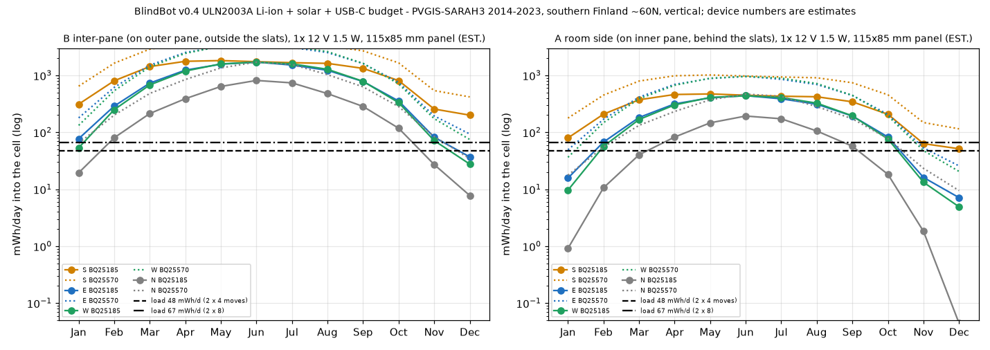
Verdict for southern Finland, v0.2 LiFePO4 design (ESTIMATES)#
- December alone does not pay for itself except on a south window with a clear view of the low sun. December harvest is ~6-17 mWh/day on a typical E/W/N or shaded window vs ~39 mWh/day of load.
- Year-round is viable through the battery buffer: the deficit from about mid-November to early February is ≈ 1-3 Wh, against ≈ 4.3 Wh usable. From late February to October the panel refills the cell in days.
- Marginal cases: north windows, heavily shaded windows, or slats kept closed all day in winter. Expect one USB-C top-up in January/February, or use placement B, a 100 cm² panel, or one blind per cell. The firmware's low-battery policy (section 8) stretches the reserve further.
- Measure before trusting this: put the VEML7700 where the panel will go, log lux for a winter week, and calibrate the model (section 11).
B7. USB-C backup charge path#
- The USB-C on the box (J1, 5k1 CC pull-downs, PTC) goes to CN3058E (3.6 V LFP, ISET ≈ 500 mA → about 3-4 h from empty, est.) and to BAT+. The BQ25570 keeps running in parallel; both regulate to ≤ 3.6 V.
- Motors and MCU always run from the cell, so USB only charges. A USB-C power bank for an hour is enough in a dark winter (about 1.5 Wh per hour of charging, est.).
- The XIAO's own USB-C is for programming only. Don't plug both in the solar variant unless the XIAO is isolated from 3V3_SYS (it would back-drive the rail).
- CN3058E TEMP pin: an NTC on the cell (or GND per the datasheet if unused). The box is on the room side, so no cold charging.
B8. Matter: Power Source cluster + low-battery behaviour#
Cluster (stub in firmware/main/power_source.cpp, API names checked against esp-matter release/v1.4
headers): Power Source (0x002F) on endpoint 0, features Battery + Rechargeable, EndpointList = the
window-covering endpoints.
| Attribute | Use |
|---|---|
| Status / Order / Description | Active / 0 / "LiFePO4 18650 + solar" |
| BatVoltage | rest voltage in mV (ADC on D2, motor rail off) |
| BatPercentRemaining | half-percent (0-200) from the energy ledger |
| BatChargeLevel | OK ≥ 25 %, Warning 10-25 %, Critical < 10 % (controllers raise low-battery alerts from this) |
| BatChargeState | IsCharging (rest voltage rising) / IsAtFullCharge (≥ 3.40 V) / IsNotCharging - heuristic, there is no current sensor |
| BatReplaceability / BatCapacity / BatFunctionalWhileCharging | UserReplaceable / 1500 / true |
| (optional) a second Power Source instance with Wired on its own endpoint for USB-C | TODO |
ICD/SED: sdkconfig.defaults.battery (MTD + ICD server, slow poll 5 s). A 5 s slow poll ≈ 5 s command
latency - fine for blinds; longer polls save energy. Limit Thread TX power to about 0-9 dBm (TX peak 119 mA at
0 dBm vs 305 mA at 20 dBm, C6 datasheet).
SOC on LiFePO4: the voltage plateau (~3.2-3.3 V) says almost nothing, so SOC = energy ledger (sleep µA x time + motor-seconds x energy per move, plus harvest credit from VEML7700 lux x a learned factor (TODO)), re-anchored at the plateau ends: ≥ 3.40 V after charging = 100 %, ≤ 3.18 V knee ≈ 12 %, ≤ 3.10 V ≈ 5 %, 3.00 V = 0 % (generic LFP curve, est.).
Adaptive move scheduling (firmware/main/power_policy.cpp):
| Level | SOC | Behaviour |
|---|---|---|
| NORMAL | ≥ 40 % | everything; daily re-home |
| ECO | 25-40 % | drop moves < 10 % tilt; weekly re-home |
| LOW (Warning) | 10-25 % | per-blind daily move budget derived from the reserve (1-4 moves); optional harvest parking (VT_HARVEST_PARKING, opt-in: park slats horizontal in daylight so a placement-A panel gets light) |
| CRITICAL | < 10 % | only the box button or moves toward open/horizontal; no re-home |
| EMPTY | VBAT_OK falls at 3.0 V | hardware cuts the ESP32 rail; the BQ25570 keeps harvesting; the node reboots at 3.2 V and re-joins Thread |
| always | - | a move is aborted if VBAT sags < 2.95 V under motor load; the button always wins |
Deferred moves aren't errors in Matter terms. The firmware should re-report Target = Current so controllers don't show a phantom move (TODO, verify the esp-matter behaviour).
B9. Mechanical placement + looks#
A välikaihdin sits between the inner and outer panes, so the panel can be:
| Light | Install | Looks | Verdict | |
|---|---|---|---|---|
| A | through the slats (≈ 50 % open, ≈ 10 % closed) + 3 panes | trivial, reversible, no sash opening | a dark strip at the bottom corner; the back faces the room, so print or paint a white (RAL 9010) frame/back cover to match the knob/cap. From outside: a small dark strip behind the slats | Recommended |
| B | ≈ 2x A, independent of slat angle | open the inner sash; the panel must not touch the slats or the cords; check the gasket closes over the FFC; the gap gets cold and can condense - the panel is fine, the battery stays in the room | invisible from the room behind the slats; visible from outside | Best harvest, more fiddly - do it if A's winter log is poor |
| C | indoor light only | easy | - | Not viable (~1 mWh/day in Dec) |
Keep the panel ≥ 10 mm from the glass edge seal. Don't cover the sash lock. Cable: the same white flat cable + clips as the motor cables, joining the box via a JST-PH 2-pin. The VEML7700 goes next to the panel (same light), on a 4-wire tail, or inside the box behind a light pipe if you only want room light.
B10. Electronics changes (summary - netlist in electronics/ELECTRONICS.md §10)#
- New: PV1, U5 BQ25570, U6 CN3058E, BT1 LFP 18650 + 1S protection + F2, U7 system load switch (VIN = BAT+, ON = VBAT_OK), U8 TPS61023 5.2 V boost (EN = MOT_PWR_EN), U9 VIO load switch, U10 VEML7700, 1M/1M VBAT divider.
- Pins: STEP_B → D3/GPIO21, DIR_B = DIR_A (D1, shared; one motor at a time), D2/GPIO2 = VBAT_SENSE (ADC1 ch2),
D10/GPIO18 = MOT_PWR_EN (100k pull-down), LED → on-board GPIO15. Firmware:
-D VT_POWER_SOLAR=1. - The TMC2209 is re-configured over UART after every motor-rail power-up (its registers are volatile). The UART TX goes hi-Z and STEP/DIR/EN_N go low while the rail is off, so nothing back-powers the driver. The EN_N 10k pull-up goes to VIO_MOT (gated).
B11. Bench / field tests (add to DESIGN §16)#
- Sleep current of the whole node (PPK2 or µA meter at the cell) after commissioning: target ≤ 150 µA avg.
- Motor move energy: integrate cell current over a 0→100 % move (expect ~3 mWh).
- Panel I-V at the planned spot (placement A, slats horizontal / closed), a sunny and an overcast winter day.
- A week of VEML7700 lux logging at the panel spot in Nov-Dec → calibrate
ETA_SYS/Tintools/power_budget.py. - BQ25570 dividers: verify OV 3.50 V, VBAT_OK 3.00/3.20 V with a bench supply in place of the cell.
- Brown-out: run a move at 3.0 V cell; the loaded-sag abort must trigger before the rail drops.
B12. Risks#
| Risk | Mitigation |
|---|---|
| XIAO 3V3 back-feed behaviour undocumented | test; v2 custom PCB with ESP32-C6-MINI-1 |
| Thread SED current higher than 150 µA (esp-matter config, LED, pull-ups) | measure; longer poll; 1 blind per cell |
| Panel Voc too high for the BQ25570 with LFP (OV > VIN rule) | 4-5 cell low-voltage panel; or SPV1050 with a 5 V panel |
| User keeps slats closed all winter (placement A) | placement B; opt-in harvest parking; USB top-up |
| BQ25570 internal PFET current | system and motor loads taken from BAT+ directly (VSTOR only for charging) |
| LFP SOC uncertainty | ledger + anchors; conservative bands; Critical alarm early |
B13. About REA (https://github.com/morluto/rea)#
Cloned and README read (2026-10-17). REA is an MCP/CLI toolkit for reverse-engineering software
artefacts: native binaries (Hopper/Ghidra/IDA), JS/Electron, .NET, Android APKs, firmware images
(binwalk/unblob), packet captures, logic-signal recordings, websites. It has no feature for FCC PDFs or teardown
photos. The public material here (PDF exhibits, photos, manuals, web pages) was handled with poppler
(pdfimages) + PIL crops instead. REA was not installed or used: no public Blind Tilt firmware image
exists, and analysing the SwitchBot app wouldn't reveal the power hardware. It would help later for BlindBot itself:
analyze our own ESP-IDF ELF (symbols/sections), decode Thread/BLE pcaps of the ICD poll pattern, or decode
a sigrok capture of the TMC2209 UART. All of that is our own material.
Figures
docs/power_budget.png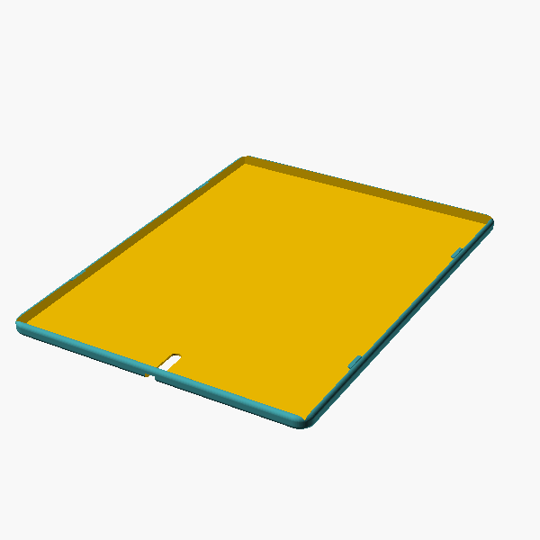
hardware/renders/pane_pack_panel_only.png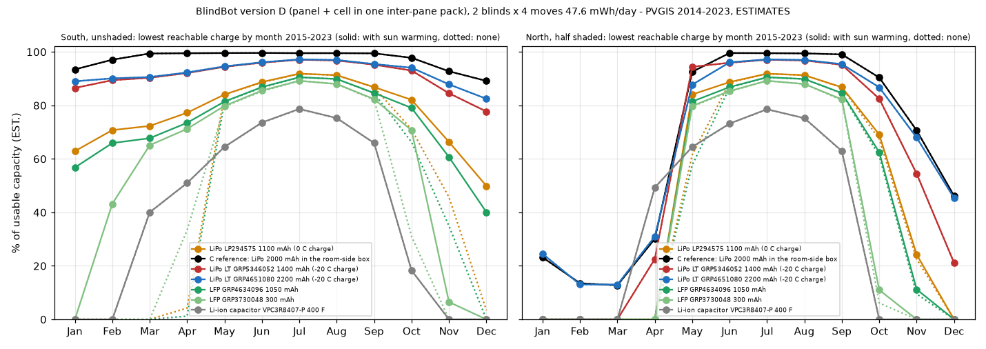
docs/power_budget_D.png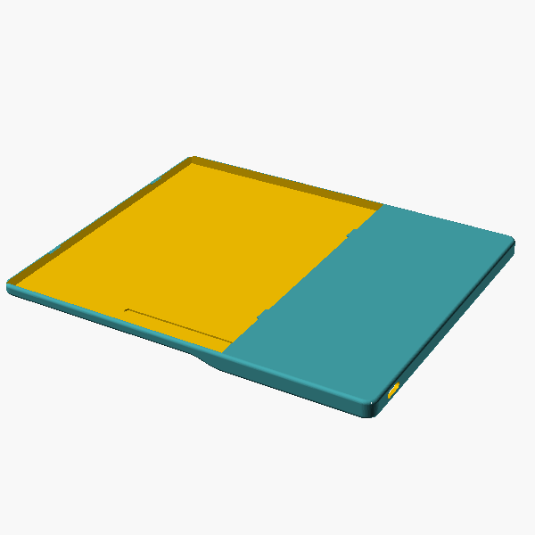
hardware/renders/pane_pack_combined_D.png